Quantcast
Channel: interfacing | Battery Guide
Viewing all 111 articles
Browse latest View live

PIC32MX: Interfacing to a Secure Digital (SD) Flash Card

$
0
0

Original Assignment

Do not erase this section!

Your assignment is to create code that will allow the PIC32 to read and write data to a FAT32 SD card. The SD card should be able to be read by a PC after data has been written on it by the PIC32.

Create functions so that it is easy to read, write and initialize the SD card.

Use the example projects in the “Microchip Solutions/USB Device – Mass Storage – SD card data logger” and “Microchip Solutions/USB Device – Mass Storage – SD card reader” folders as a guide.

Use your code to create a folder on the PIC32 and write 1000 bytes of data to a text file in that folder. How long does it take? Make sure the PC can read the file.

Interfacing to a Secure Digital (SD) Flash Card

Create a folder on the SD card with the PC and place a text file in the folder with 1000 bytes of data. Read the file with the PIC32. How long does it take?

Overview

Secure digital cards, or SD cards, are inexpensive and common mass storage devices that can be interfaced with our PIC to provide a larger non-volatile data storage space. Non-volatile memory is computer memory that retains information even when not powered. In this lab, we interfaced our PIC32MX460F512L to communicate with a 2GB FAT32 SD card to allow reading and writing of data.

The original program stems from tutorials from the book Programming 32-bit Microcontrollers in C: Exploring the PIC32 by Lucio Di Jasio. We used the tutorials from Day 14 and 15 to generate our code for SD card reading and writing via SPI communication (Serial Peripheral Interface). The main problem with this tutorial is that it is made for the PIC32MX360F512L on the Explorer16 board, so many changes were required in order to run the code.

NOTE: While ultimately, we were able to initialize the SD card and send data along the output and input lines, we were unsuccessful in executing the read/write demo. We are confident that the hardware configuration and circuit are correct, however the code likely contains errors.

Circuit

The SD card holder has 11 pins, 6 of which are being directly used for communication with our PIC. The SD card is powered off of 3.3V from our PIC, which comes from our mini-usb connection. 10K and 1K resistors pull-up resistors were added to each connection in order to allow for a voltage drop. Green and yellow LEDs were added to the Write Protect (WP) and Card Detect (CD) lines for ease of use. A powered yellow LED indicates the presence of an SD card in the SD card reader. A powered green LED indicates that the Write Protect is off. No resistor is necessary on the clock line. The IRQ and P9 pins on the SD card holder were not needed for SPI communication, so they were not connected to the PIC. However, they need to be powered for the SD card holder to operate properly. A breakdown of each of the 11 pins on the SD card holder is displayed in the table below.

NOTE: While ultimately, we were able to initialize the SD card and send data along the output and input lines, we were unsuccessful in executing the read/write demo. We are confident that the hardware configuration and circuit are correct, however the code likely contains errors.

Interfacing to a Secure Digital (SD) Flash Card

Circuit

The SD card holder has 11 pins, 6 of which are being directly used for communication with our PIC. The SD card is powered off of 3.3V from our PIC, which comes from our mini-usb connection. 10K and 1K resistors pull-up resistors were added to each connection in order to allow for a voltage drop. Green and yellow LEDs were added to the Write Protect (WP) and Card Detect (CD) lines for ease of use. A powered yellow LED indicates the presence of an SD card in the SD card reader. A powered green LED indicates that the Write Protect is off. No resistor is necessary on the clock line. The IRQ and P9 pins on the SD card holder were not needed for SPI communication, so they were not connected to the PIC. However, they need to be powered for the SD card holder to operate properly. A breakdown of each of the 11 pins on the SD card holder is displayed in the table below.

NOTE: While ultimately, we were able to initialize the SD card and send data along the output and input lines, we were unsuccessful in executing the read/write demo. We are confident that the hardware configuration and circuit are correct, however the code likely contains errors.


For more detail: PIC32MX: Interfacing to a Secure Digital (SD) Flash Card

Current Project / Post can also be found using:

  • pic32 sd card
  • pic32mx projects

The post PIC32MX: Interfacing to a Secure Digital (SD) Flash Card appeared first on PIC Microcontroller.


Interfacing DHT11 humidity and temperature sensor with PIC16F877A using pic microcontoller

$
0
0

After interfacing the DHT11 with Arduino uno board at the following post:
ARDUINO Humidity & Temperature Measurement Using DHT11 Sensor
Now we are going to see how to interface this sensor with microchip pic16f877a.
There are some descriptions of how this sensor work  in the above link

A brief description of the code:
The code is written using MikroC compiler.
 First we must send a start signal to the sensor, we do that by configuring the pic pin connected to the sensor as output, the mcu sends 0 for 18ms then sends 1 for 30us.
After sending start signal to the sensor, the sensor will send a response signal to the mcu. To detect this signal mcu pin must be configured as input.
When the sensor finishes the response signal, it begins sending humidity and temperature data serially.
If there is a problem with the sensor or there is no sensor connected to the circuit, the LCD displays “there is no response from the sensor”. And if there is a problem in the sensor which means the values are incorrect the LCD displays “Check sum error”.
Interfacing DHT11 humidity and temperature sensor with PIC16F877A
// LCD module connections
 sbit LCD_RS at RB5_bit;
 sbit LCD_EN at RB4_bit;
 sbit LCD_D4 at RB3_bit;
 sbit LCD_D5 at RB2_bit;
 sbit LCD_D6 at RB1_bit;
 sbit LCD_D7 at RB0_bit;
 sbit LCD_RS_Direction at TRISB5_bit;
 sbit LCD_EN_Direction at TRISB4_bit;
 sbit LCD_D4_Direction at TRISB3_bit;
 sbit LCD_D5_Direction at TRISB2_bit;
 sbit LCD_D6_Direction at TRISB1_bit; 
 sbit LCD_D7_Direction at TRISB0_bit;
 // End LCD module connections
 char *text,mytext[4];
 unsigned char  a = 0, b = 0,i = 0,t1 = 0,t2 = 0,
               rh1 = 0,rh2 = 0,sum = 0;
 void StartSignal(){
 TRISD.F2 = 0;    //Configure RD2 as output
 PORTD.F2 = 0;    //RD2 sends 0 to the sensor
 delay_ms(18);
 PORTD.F2 = 1;    //RD2 sends 1 to the sensor
 delay_us(30);
 TRISD.F2 = 1;    //Configure RD2 as input
  }
 void CheckResponse(){
 a = 0;
 delay_us(40);
 if (PORTD.F2 == 0){
 delay_us(80);
 if (PORTD.F2 == 1)   a = 1;   delay_us(40);}
 }
 void ReadData(){
 for(b=0;b<8;b++){
 while(!PORTD.F2); //Wait until PORTD.F2 goes HIGH
 delay_us(30);
 if(PORTD.F2 == 0)    i&=~(1<<(7-b));  //Clear bit (7-b)
 else{i|= (1<<(7-b));               //Set bit (7-b)
 while(PORTD.F2);}  //Wait until PORTD.F2 goes LOW
 }
 }
 void main() {
 TRISB = 0;        //Configure PORTB as output
 PORTB = 0;        //Initial value of PORTB
 Lcd_Init();
 while(1){
 Lcd_Cmd(_LCD_CURSOR_OFF);        // cursor off
 Lcd_Cmd(_LCD_CLEAR);             // clear LCD
  StartSignal();
  CheckResponse();
  if(a == 1){
  ReadData();
  rh1 =i;
  ReadData();
  rh2 =i;
  ReadData();
  t1 =i;
  ReadData();
  t2 =i;
  ReadData();
  sum = i;
  if(sum == rh1+rh2+t1+t2){
  text = "Temp:  .0C";
  Lcd_Out(1,6,text);
  text = "Humidity:  .0%";
  Lcd_Out(2,2,text);
  ByteToStr(t1,mytext);
  Lcd_Out(1,11,Ltrim(mytext));
  ByteToStr(rh1,mytext);
  Lcd_Out(2,11,Ltrim(mytext));}
  else{
  Lcd_Cmd(_LCD_CURSOR_OFF);        // cursor off
  Lcd_Cmd(_LCD_CLEAR);             // clear LCD
  text = "Check sum error";
  Lcd_Out(1,1,text);}
  }
  else { 
  text="No response";
  Lcd_Out(1,3,text);
  text = "from the sensor";
  Lcd_Out(2,1,text);
  }
  delay_ms(2000);
  }
  }

Saturday, November 8, 2014

PIC16F877A LCD Example

This is just an example to show how to interface 16×2 lcd with pic16f877a. The lcd is going to display “PIC16F877A” in the the first line and “LCD Example” in the second line. The code is written using MikroC compiler.
// LCD module connections
sbit LCD_RS at RB5_bit;
sbit LCD_EN at RB4_bit;
sbit LCD_D4 at RB3_bit;
sbit LCD_D5 at RB2_bit;
sbit LCD_D6 at RB1_bit;
sbit LCD_D7 at RB0_bit;
sbit LCD_RS_Direction at TRISB5_bit;
sbit LCD_EN_Direction at TRISB4_bit;
sbit LCD_D4_Direction at TRISB3_bit;
sbit LCD_D5_Direction at TRISB2_bit;
sbit LCD_D6_Direction at TRISB1_bit;
sbit LCD_D7_Direction at TRISB0_bit;
// End LCD module connections
char *text;
void main() {
TRISB = 0;
PORTB = 0;
Lcd_Init();
Lcd_Cmd(_LCD_CURSOR_OFF);        // cursor off
Lcd_Cmd(_LCD_CLEAR);             // clear LCD
text = "PIC16F877A" ;
Lcd_Out(1,4,text);
text = "LCD Example";
Lcd_Out(2,4,text);
while(1);                     //infinite loop
}

Interfacing DHT11 humidity and temperature sensor with PIC16F877ATuesday, November 4, 2014

Real Time Clock

Now, I’m going to work with real time clocks, for that I will use the integrated circuit DS1307serial real time clock. I will use this ic with Arduino uno board and also I have to return to the pic microcontroller chip PIC16F877A. For the pic mcu I will use Microc and the full codes and schematics will be available on the next posts.
The DS1307 provides clock and calender. The clock shows seconds, minutes and hours and the calender shows day, month and year. The ds1307 uses I2C serial interface to transfer information with the microcontroller. More information in its datasheet.

Cd-Rom 3 phase Sensored BLDC Motor Arduino Controller

BLDC (brushless dc) motors are three phase dc motors, unlike the simple dc motors the bldc motors are more difficult to control. These motors are used in many applications for examples rc airplans and rc cars.
In this post we will see how to control cd-rom sensored BLDC motor using Arduino uno board. But first there are some things we should know in order to control the motor in easy way.
The bldc motor that we are going to use is sensored via hall effect sensors (position sensors) attached with the motor(3 sensors). Each sensor outputs digital high for 180 electrical degrees and low for the other 180 electrical degrees.these sensors are used to tell us where is the position of the motor, then when we know the position of the motor we will energize just tow windings (of three). The below figure shows how sensors outputs and the corresponding voltage applied to the motor:

Current Project / Post can also be found using:

  • simple mikroc program for dht11

The post Interfacing DHT11 humidity and temperature sensor with PIC16F877A using pic microcontoller appeared first on PIC Microcontroller.

Interfacing PIR sensor to 8051

$
0
0

PIR sensors are widely used in motion detecting devices. This article is about interfacing a PIR sensor to 8051 microcontroller. A practical intruder alarm system using PIR sensor and 8051 microcontroller is also included at the end of this article. Before going in to the core of the article, let’s have a look at the PIR sensor and its working.

PIR sensor.

PIR sensor is the abbreviation of Passive Infrared Sensor. It measures the amount of infrared energy radiated by objects in front of it. They does not  emit any kind of radiation but senses the infrared waves emitted or reflected by objects. The heart of a PIR sensor is a solid state sensor or an array of such sensors constructed from pyro-electric materials. Pyro-electric material is material by virtue of it generates energy when exposed to radiation.Gallium Nitride is the most common material used for constructing PIR sensors. Suitable lenses are mounted at the front of the sensor to focus the incoming radiation to the sensor face. When ever an object or a human passes across the sensor the intensity of the of the incoming radiation with respect to the background increases. As a result the energy generated by the sensor also increases. Suitable signal conditioning circuits convert the energy generated by the sensor to a suitable voltage output. In simple words the output of a PIR sensor module will be HIGH when there is motion in its field of view and the output will be LOW when there is no motion.

Interfacing PIR sensor to 8051DSN-FIR800 is the PIR sensor module used in this project.Its image  is shown above.  It operates from 4.5 to 5V supply and the stand by current is less than 60uA. The output voltage will be 3.3V when the motion is detected and 0V when there is no motion. The sensing angle cone is 110° and the sensing range is 7 meters. The default delay time is 5 seconds. There are two preset resistor on the sensor module. One is used for adjusting the delay time and the other is used for adjusting the sensitivity. Refer the datasheet of DSN-FIR800 for knowing more.

Interfacing PIR sensor to 8051.

The 8051 considers any voltage between 2 and 5V at its port pin as HIGH and any voltage between 0 to 0.8V as LOW. Since the output of the PIR sensor module has only two stages (HIGH (3.3V) and LOW (0V)) , it can be directly interfaced to the 8051 microcontroller.

The circuit shown above will read the status of the output of the PIR sensor and switch ON the LED when there is a motion detected and switch OFF the LED when there is no motion detected. Output pin of the PIR sensor is connected to Port 3.5 pin of the 8051. Resistor R1, capacitor C1 and push button switch S1 forms the reset circuit. Capacitors C3,C4 and crystal X1 are associated with the oscillator circuit. C2 is just a decoupling capacitor. LED is connected through Port  2.0 of the microcontroller. Transistor Q1 is used for switching the LED. R2 limits the base current of the transistor and R3 limits the current through the LED. Program for interfacing PIR sensor to 8051 is shown below.

Program.

PIR EQU P3.5
LED EQU P2.0
ORG 00H
CLR P2.0         
SETB P3.5
HERE:JNB PIR, HERE
     SETB LED
HERE1:JB PIR,HERE1
      CLR LED
SJMP HERE
END

The status of the output of the PIR sensor is checked using JNB and JB instructions. Code “HERE:JNB PIR, HERE” loops there until the output of the PIR sensor is HIGH. When it becomes HIGH it means a motion detected and the program sets P2.O HIGH in order to make the LED ON. The output pin of the PIR sensor remains HIGH for 5 seconds after a motion is detected. Code”HERE1:JB PIR,HERE1″ loops there until the output of the PIR sensor becomes LOW. When it becomes LOW the loop is exited and Port 2.0 is made LOW for switching OFF the LED. Then the program jumps back to label “HERE” and the entire cycle is repeated.


For more detail: Interfacing PIR sensor to 8051

Current Project / Post can also be found using:

  • interfacing pir sensor with 8051
  • pir sensor and 8051 interfacing
  • pir sensor interfacing with 8051
  • pirsensor interfacing with 8051 pdf

The post Interfacing PIR sensor to 8051 appeared first on PIC Microcontroller.

PIC’ing the MAX5581: Interfacing a PIC Microcontroller with the MAX5581 Fast-Settling DAC

$
0
0

MAX5581 Overview

The MAX5581 is a 12-bit, fast-settling DAC featuring a 3-wire SPI™ serial interface. The MAX5581’s interface can support SPI up to 20MHz with a maximum settling time of 3µs. This application note presents an application circuit and all the firmware required to interface the fastest line of PIC microcontrollers (PIC18F core) to the MAX5581 DAC. The example assembly program was written specifically for the PIC18F442 using the free assembler provided in MPLAB IDE version 6.10.0.0.

Hardware Overview

The application circuit discussed here uses the MAX5581 Evaluation (EV) Kit, which consists of the MAX5581, an ultra-high-precision voltage reference (MAX6126), two pushbutton switches, gain setting resistors, and a proven PCB layout. The PIC18F442 is not present on the MAX5581EVKIT board, but was added to the system to complete the application schematic shown in Figure 1. The /CS\, SCLK, DIN, and DOUT pads on the MAX5581EVKIT allow an easy connection for the SPI serial interface.

PIC'ing the MAX5581: Interfacing a PIC Microcontroller with the MAX5581 Fast-Settling DAC

Analog and Digital Ground Planes

It is good practice to separate the analog and digital ground planes, as shown in Figure 2. Use a ferrite bead, such as the TDK MMZ1608B601C, to connect both ground planes together through a ferrite bead. This prevents the microcontroller’s system clock and its harmonics from feeding into the analog ground. Knowing that the PIC18F442’s system clock is 40MHz, the MMZ1608B601C was chosen for its specific impedance vs. frequency characteristics. Figure 3 shows the impedance versus frequency curve for the MMZ1608B601C.

Firmware Overview

The example assembly program shown in Listing 1 initializes the MAX5581 using the PIC18F442’s internal MSSP SPI peripheral. The PIC18F442’s 40MHz system clock allows the MSSP to provide an SPI clock (SCLK) up to 10MHz. Table 1 shows the only configuration word required after power. Once the MAX5581 is initialized, the program constantly loads the DAC output registers with zero scale followed by full scale, as shown in Table 2. This constant loop results in a square wave, shown in Figure 4, which demonstrates the fast settling time of the MAX5581.

Listing 1.asm

;******************************************************************************
;
;    Filename:		Listing 1 (Absolute Code Version)
;    Date:    		2/25/05
;    File Version:  	1.0
;
;    Author:        	Ted Salazar
;    Company:       	Maxim
;
;******************************************************************************
;
;	Program Description:
;
;	This program interfaces the internal SPI MSSP
;	(Peripheral) of the PIC18F442 to the MAX5581 SPI
;	Quad DAC. The program initializes the MAX5581
;	and dynamically generates a 50% duty cycle square
;	wave with a frequency of 80KHz.
;
;
;******************************************************************************
;
; History:
; 2/25/05: Tested SPI DAC format
; 2/25/05: Initialized MAX5591
; 12/14/04: Cleared tcount timer in HWSPI_W_spidata_W
;******************************************************************************
;******************************************************************************


;
;******************************************************************************
;
;    Files required:         P18F442.INC
;
;******************************************************************************
	radix hex               ;Default to HEX
	LIST P=18F442, F=INHX32	;Directive to define processor and file format
	#include 	;Microchip's Include File
;******************************************************************************
;******************************************************************************
xmit    equ		06 		; Asynchronous TX is at C6
;
;******************************************************************************
;Configuration bits
; The __CONFIG directive defines configuration data within the .ASM file.
; The labels following the directive are defined in the P18F442.INC file.
; The PIC18FXX2 Data Sheet explains the functions of the configuration bits.
; Change the following lines to suit your application.

;T	__CONFIG	_CONFIG1H, _OSCS_OFF_1H & _RCIO_OSC_1H
;T	__CONFIG	_CONFIG2L, _BOR_ON_2L & _BORV_20_2L & _PWRT_OFF_2L
;T	__CONFIG	_CONFIG2H, _WDT_ON_2H & _WDTPS_128_2H
;T	__CONFIG	_CONFIG3H, _CCP2MX_ON_3H
;T	__CONFIG	_CONFIG4L, _STVR_ON_4L & _LVP_OFF_4L & _DEBUG_OFF_4L
;T	__CONFIG	_CONFIG5L, _CP0_OFF_5L & _CP1_OFF_5L & _CP2_OFF_5L & _CP3_OFF_5L
;T	__CONFIG	_CONFIG5H, _CPB_ON_5H & _CPD_OFF_5H
;T	__CONFIG	_CONFIG6L, _WRT0_OFF_6L & _WRT1_OFF_6L & _WRT2_OFF_6L & _WRT3_OFF_6L
;T	__CONFIG	_CONFIG6H, _WRTC_OFF_6H & _WRTB_OFF_6H & _WRTD_OFF_6H
;T	__CONFIG	_CONFIG7L, _EBTR0_OFF_7L & _EBTR1_OFF_7L & _EBTR2_OFF_7L & _EBTR3_OFF_7L
;T	__CONFIG	_CONFIG7H, _EBTRB_OFF_7H

;******************************************************************************
;Variable definitions
; These variables are only needed if low priority interrupts are used.
; More variables may be needed to store other special function registers used
; in the interrupt routines.
 PIC'ing the MAX5581 Interfacing a PIC Microcontroller with the MAX5581 Fast-Settling DAC Schematic		CBLOCK	0x080
		WREG_TEMP	;variable used for context saving
		STATUS_TEMP	;variable used for context saving
		BSR_TEMP	;variable used for context saving
		;
		ENDC

		CBLOCK	0x000
		EXAMPLE	;example of a variable in access RAM
		;
		temp    	;
		temp2
		;
		xmtreg  	;
		cntrb   	;
		cntra   	;
		bitctr  	;

		tcount	;
		speedLbyte	;T Being used in HWSPI_speed
		;
		ENDC
;******************************************************************************
;Reset vector
; This code will start executing when a reset occurs.

		ORG	0x0000

		goto	Main	;go to start of main code

;******************************************************************************
;High priority interrupt vector
; This code will start executing when a high priority interrupt occurs or
; when any interrupt occurs if interrupt priorities are not enabled.

		ORG	0x0008

		bra	HighInt	;go to high priority interrupt routine

;******************************************************************************
;Low priority interrupt vector and routine
; This code will start executing when a low priority interrupt occurs.
; This code can be removed if low priority interrupts are not used.

		ORG	0x0018

		movff	STATUS,STATUS_TEMP	;save STATUS register
		movff	WREG,WREG_TEMP		;save working register
		movff	BSR,BSR_TEMP		;save BSR register

;	*** low priority interrupt code goes here ***


		movff	BSR_TEMP,BSR		;restore BSR register
		movff	WREG_TEMP,WREG		;restore working register
		movff	STATUS_TEMP,STATUS	;restore STATUS register
		retfie

;******************************************************************************
;High priority interrupt routine
; The high priority interrupt code is placed here to avoid conflicting with
; the low priority interrupt vector.

HighInt:

;	*** high priority interrupt code goes here ***


For more detail: PIC’ing the MAX5581: Interfacing a PIC Microcontroller with the MAX5581 Fast-Settling DAC

Current Project / Post can also be found using:

  • DAC using pic 18f4520

The post PIC’ing the MAX5581: Interfacing a PIC Microcontroller with the MAX5581 Fast-Settling DAC appeared first on PIC Microcontroller.

PC Interfacing a GameBoy Camera using PIC18F4620 microcontroller

$
0
0

PC Interfacing a GameBoy Camera


Here’s another past project of mine from a couple of years ago. At that time I was looking for a low-res camera for simple robotics image processing, and all I had experience with was PIC (12, 16, and 18) microcontrollers. So I didn’t really get to work on the images real time (not enough RAM or speed, and I could not find any suitable SRAM around at that time). I think I’ll revisit this project later on using my new TI Stellaris Board.
GameBoy Camera
The system consists of a GameBoy Camera (Mitsubishi M64282FP Image Sensor with hardware image processing), an ADC0820 high-speed ADC to convert analog pixel values to digital (the sensor outputs pixels as 2.0V p-p analog values), a LM385-2V5 2.5V micropower voltage reference IC, a PIC18F4660 for processing the digital values to send them later on to a PC via the serial port (or USB with a RS-232 – USB converter).The PC part of the project is a program (uses OpenGL to display the received image, the height of the pixels change according to brightness to have a fake 3D effect) written on Borland C++  Builder. I also still have the simple test programs written in Processing (brightness tracking, etc.). All will be attached.

Step 1

PC Interfacing a GameBoy Camera

Since the code and the schematics are self explanatory, and the datasheet for the MCU and the image sensor are rather informative, I’m not going to get into much theory here (as always, questions are answered). Here’s the flowchart of the system, which explains what’s going on.  Ignore the USART part (old version), registers are set up from the MCU :) And an animated GIF image showing brightness tracking done with this camera in Processing.The first thing to do before you start is to create a suitable connector for the camera (after opening the cartridge structured box with a tri-wing screwdriver and disconnecting / removing the camera from the main structure). I attached a picture of the pinout, so many people used this image, so I don’t know who to give the credit (here’s one http://www.seattlerobotics.org/encoder/200205/gbcam.html). I used an IDC-10 connector to connect it to my old PIC board (from another project).In the next step we’ll be looking at the schematics and how the system actually functions.

Step 2

schematics and how the system actually functions

This is the card connected to my old PIC board. Since I had one laying around, I just made an expansion card to it for this project.
PORTC of the PIC is used for communicating with the camera, PORTD is dedicated to the 8-bit ADC output, and PORTB is used for the ADC’s CS and servos, which I didn’t really manage to control at that time (I tried observing pixel values on the fly, finding the brightest first pixel’s coordinates with a small formula, and adjusting the servo angles in accordance). Servos just went crazy, and I lost patience :|

The LED’s are for displaying board power and frame capture. The schematics are a bit tangled since I didn’t care much about pin labeling then (to quickly create the PCB), so please have patience. I’m not going to attach the PIC board schematic and PCB files (but please pay attention to the pictures for pin orientation), since it’s basically a 40-pin PIC board with a crystal, and all the ports are connected to IDC-10 connectors.

The pinout of the M6428FN connector in the schematic is as follows, so you can make a simpler adapter / connector for the camera as you see in the picture:

1- GND

2- Vout to ADC (Image data in analog)

3- Bit-bang XCK for SIN, RESET, LOAD, and START (and 10 KHz PWM with 50% DC to get the pixel values), also triggers ADC
conversion for each pixel value (74HC14 inverts this signal for the ADC to start the conversion), after a successfull read, ADC sends and interrupt to the PIC, and the PIC sends the digital value to its USART, which finally goes to our PC.

4- LOAD signal to camera (Parameter Register Set Enable)

5- START signal to camera (Start Image Sensing)

6- VCC (all the analog and digital power)

7- SIN signal to write the regs on the camera (Parameter Data Input)

8- RESET signal to camera (Reset Parameter Registers)

9- READ (Image) signal from camera

10- GND

For more info on these pins, please refer to the image sensor datasheet attached on the next steps. You’ll understand the schematics better when you read the comments in the code files.

For more detail: PC Interfacing a GameBoy Camera using PIC18F4620 microcontroller

Current Project / Post can also be found using:

  • images of microcontroller connected with pc and camera

The post PC Interfacing a GameBoy Camera using PIC18F4620 microcontroller appeared first on PIC Microcontroller.

Interfacing with The Energy Detective using pic microcontoller

$
0
0

I recently bought The Energy Detective (TED), a pretty inexpensive and friendly way to keep tabs on your whole house’s electricity usage. It’s a lot like having a more featureful version of your utility company’s power meter, sitting on your kitchen counter. It can estimate your utility bill, and tell you how much electricity and money you’re using in real-time. The resolution is pretty good- 10 watts, 1 second.

As a product, I’ve been pretty happy with it. It does what it claims to, and the measurements seem to be fast and accurate. Of course, being the crazy hacker I am, I wanted to interface TED with other things. I don’t have a home automation system as such, but I did want to get real-time graphs of my electricity usage over various time periods. I also wanted the possibility to use TED as an information feed for various other display devices around the house. (But that’s a topic for another blog post…)

Interfacing with The Energy DetectiveThe stock TED package consists of two pieces: A measurement/transmit unit (MTU) and receive/display unit (RDU). The MTU has a pair of current transformers, and it installs entirely in your house’s breaker panel. It takes the power readings every second, and transmits them over the power lines to the RDU, which is just a little LCD panel that plugs into the wall. The RDU has a USB port, which you can use with TED’s “Footprints” software.

So, hoping that the USB port would do what I want, I bought the Footprints software for $45. The TED system itself is, in my opinion, a really good value. The Footprints software is not. As a consumer, I was disappointed by two main things:First of all- the UI lacks any polish whatsoever. It looks like a bad web page from the 90’s. Second of all, the data collection is not done in hardware, it’s implemented by a Windows service. This means you can’t collect data to graph unless you have a Windows PC running. Not exactly a power-efficient way to get detailed power usage graphs.

As a hobbyist, a few more things frustrated me about Footprints. The implementation was pretty amateurish. Their Windows service runs a minimal HTTP server which serves up data from an sqlite database in XML. The front end is actually just a Flash applet masquerading as a full application. Energy Inc, the company behind TED, has an API for Footprints: but you have to sign a legal agreement to get access to it, and I wasn’t able to get any details on what the API does and doesn’t include without signing the agreement. So, I opted not to. It would be much more fun to do a little reverse engineering…

So, I did. The end result is that I now have two ways of getting data out of my TED system.

Using the USB port

The TED RDU’s USB port is actually just a common FTDI usb-to-serial adapter. The RDU sends a binary packet every second, which includes all of the data accessible from the Footprints UI. This includes current power usage, current AC line voltage, utility rates, month-to-date totals, and anything else you’ve programmed into your RDU.

There has been some prior work on reverse engineering this protocol. The Misterhouse open source home automation project has a Perl module which can decode the TED messages.

Unfortunately, the Perl module in Misterhouse won’t work with more recent versions of the RDU like mine. The recent RDUs have a different packet length, and they require a polling command to be sent before they’ll reply with any data.

I found the correct polling command by snooping on Footprints’ serial traffic with Portmon. I also noticed a packet framing/escaping scheme, which explains some of the length variations that would have broken the module in Misterhouse.

The result is a Python module for receiving data from a TED RDU. It isn’t terribly featureful, but it should be pretty robust.

Interfacing with The Energy Detective

Direct from the wall socket

Now for the more exciting method: What about reading data directly from the power line, without using the TED receive/display unit at all? This could provide some exciting opportunities to embed a small and cheap TED receiver inside of other devices, and it would provide some insight on what exactly is being transmitted by the box in my breaker panel.

The TED RDU is pretty simple internally: A Dallas real-time clock, PIC18 microcontroller, chip-on-glass LCD, some buttons, and the TDA5051A, a single-chip home automation modem from Philips. This chip can receive and transmit ASK modulated signals at 1200 baud, with a carrier frequency of around 132 kHz.

Digi-key carries the TDA5051A, but I figured it would be more educational (and more hobbyist-friendly) to try and build a simpler receiver from scratch using only commonly available parts.


For more detail: Interfacing with The Energy Detective

The post Interfacing with The Energy Detective using pic microcontoller appeared first on PIC Microcontroller.

Interfacing the AT keyboard.

$
0
0

PC Keyboard Theory

The IBM keyboard you most probably have sitting in front of you, sends scan codes to your computer. The scan codes tell your Keyboard Bios, what keys you have pressed or released. Take for example the ‘A’ Key. The ‘A’ key has a scan code of 1C (hex). When you press the ‘A’ key, your keyboard will send 1C down it’s serial line. If you are still holding it down, for longer than it’s typematic delay, another 1C will be sent. This keeps occurring until another key has been pressed, or if the ‘A’ key has been released.

However your keyboard will also send another code when the key has been released. Take the example of the ‘A’ key again, when released, the keyboard will send F0 (hex) to tell you that the key with the proceeding scan code has been released. It will then send 1C, so you know which key has been released.

Your keyboard only has one code for each key. It doesn’t care it the shift key has been pressed. It will still send you the same code. It’s up to your keyboard BIOS to determine this and take the appropriate action. Your keyboard doesn’t even process the Num Lock, Caps Lock and Scroll Lock. When you press the Caps Lock for example, the keyboard will send the scan code for the cap locks. It is then up to your keyboard BIOS to send a code to the keyboard to turn on the Caps lock LED.
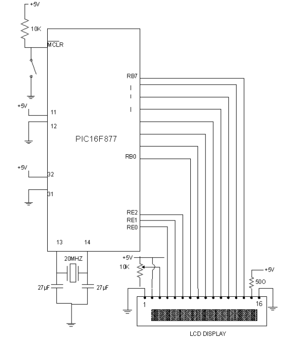
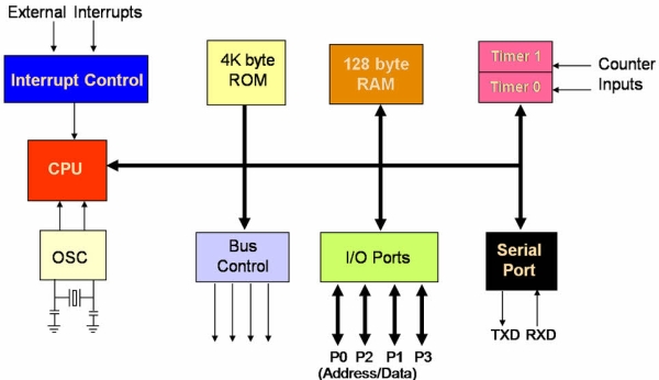
Interfacing the AT keyboard.Now there’s 101 keys and 8 bits make 256 different combinations, thus you only need to send one byte per key, right?

Nop. Unfortunately a handful of the keys found on your keyboard are extended keys, and thus require two scan code. These keys are preceded by a E0 (hex). But it doesn’t stop at two scan codes either. How about E1,14,77,E1,F0,14,F0,77! Now that can’t be a valid scan code? Wrong again. It’s happens to be sent when you press the Pause/break key. Don’t ask me why they have to make it so long! Maybe they were having a bad day or something?

When an extended key has been released, it would be expect that F0 would be sent to tell you that a key has been released. Then you would expect E0, telling you it was an extended key followed by the scan code for the key pressed. However this is not the case. E0 is sent first, followed by F0, when an extended key has been released.

Keyboard Commands

Besides Scan codes, commands can also be sent to and from the keyboard. The following section details the function of these commands. By no means is this a complete list. These are only some of the more common commands.

Host Commands

These commands are sent by the Host to the Keyboard. The most common command would be the setting/resetting of the Status Indicators (i.e. the Num lock, Caps Lock & Scroll Lock LEDs). The more common and useful commands are shown below.

ED Set Status LED’s – This command can be used to turn on and off the Num Lock, Caps Lock & Scroll Lock LED’s. After Sending ED, keyboard will reply with ACK (FA) and wait for another byte which determines their Status. Bit 0 controls the Scroll Lock, Bit 1 the Num Lock and Bit 2 the Caps lock. Bits 3 to 7 are ignored.
EE Echo – Upon sending a Echo command to the Keyboard, the keyboard should reply with a Echo (EE)
F0 Set Scan Code Set. Upon Sending F0, keyboard will reply with ACK (FA) and wait for another byte, 01-03 which determines the Scan Code Used. Sending 00 as the second byte will return the Scan Code Set currently in Use
F3 Set Typematic Repeat Rate. Keyboard will Acknowledge command with FA and wait for second byte, which determines the Typematic Repeat Rate.
F4 Keyboard Enable – Clears the keyboards output buffer, enables Keyboard Scanning and returns an Acknowledgment.
F5 Keyboard Disable – Resets the keyboard, disables Keyboard Scanning and returns an Acknowledgment.
FE Resend – Upon receipt of the resend command the keyboard will re- transmit the last byte sent.
FF Reset – Resets the Keyboard.

Commands

Now if the Host Commands are send from the host to the keyboard, then the keyboard commands must be sent from the keyboard to host. If you think this way, you must be correct. Below details some of the commands which the keyboard can send.

FA Acknowledge
AA Power On Self Test Passed (BAT Completed)
EE See Echo Command (Host Commands)
FE Resend – Upon receipt of the resend command the Host should re-transmit the last byte sent.
00 Error or Buffer Overflow
FF Error or Buffer Overflow

Scan Codes

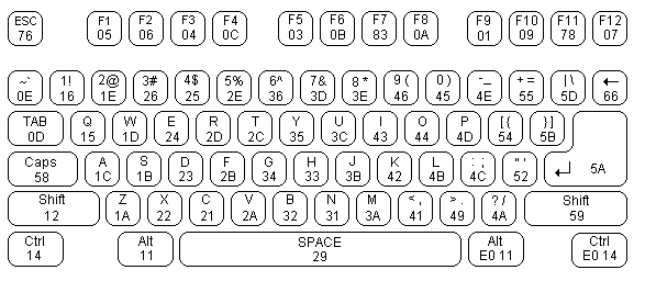
The diagram below shows the Scan Code assigned to the individual keys. The Scan code is shown on the bottom of the key. E.g. The Scan Code for ESC is 76. All the scan codes are shown in Hex.

As you can see, the scan code assignments are quite random. In many cases the easiest way to convert the scan code to ASCII would be to use a look up table. Below is the scan codes for the extended keyboard & Numeric keypad.

The Keyboard’s Connector

The PC’s AT Keyboard is connected to external equipment using four wires. These wires are shown below for the 5 Pin DIN Male Plug & PS/2 Plug.

A fifth wire can sometimes be found. This was once upon a time implemented as a Keyboard Reset, but today is left disconnected on AT Keyboards. Both the KBD Clock and KBD Data are Open Collector bi-directional I/O Lines. If desired, the Host can talk to the keyboard using these lines.

Note: Most keyboards are specified to drain a maximum 300mA. This will need to be considered when powering your devices

The Keyboard’s Protocol

Keyboard to Host

As mentioned before, the PC’s keyboard implements a bi-directional protocol. The keyboard can send data to the Host and the Host can send data to the Keyboard. The Host has the ultimate priority over direction. It can at anytime (although the not recommended) send a command to the keyboard.

The keyboard is free to send data to the host when both the KBD Data and KBD Clock lines are high (Idle). The KBD Clock line can be used as a Clear to Send line. If the host takes the KBD Clock line low, the keyboard will buffer any data until the KBD Clock is released, ie goes high. Should the Host take the KBD Data line low, then the keyboard will prepare to accept a command from the host.

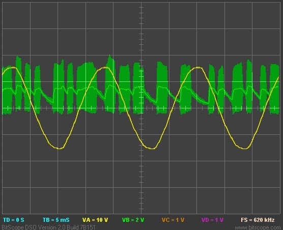
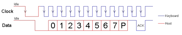
The transmission of data in the forward direction, ie Keyboard to Host is done with a frame of 11 bits. The first bit is a Start Bit (Logic 0) followed by 8 data bits (LSB First), one Parity Bit (Odd Parity) and a Stop Bit (Logic 1). Each bit should be read on the falling edge of the clock.

The above waveform represents a one byte transmission from the Keyboard. The keyboard may not generally change it’s data line on the rising edge of the clock as shown in the diagram. The data line only has to be valid on the falling edge of the clock. The Keyboard will generate the clock. The frequency of the clock signal typically ranges from 20 to 30 Khz. The Least Significant Bit is always sent first.

Host to Keyboard

The Host to Keyboard Protocol is initiated by taking the KBD data line low. However to prevent the keyboard from sending data at the same time that you attempt to send the keyboard data, it is common to take the KBD Clock line low for more than 60us. This is more than one bit length. Then the KBD data line is taken low, while the KBD clock line is released.

The keyboard will start generating a clock signal on it’s KBD clock line. This process can take up to 10mS. After the first falling edge has been detected, you can load the first data bit on the KBD Data line. This bit will be read into the keyboard on the next falling edge, after which you can place the next bit of data. This process is repeated for the 8 data bits. After the data bits come an Odd Parity Bit.

Once the Parity Bit has been sent and the KBD Data Line is in a idle (High) state for the next clock cycle, the keyboard will acknowledge the reception of the new data. The keyboard does this by taking the KBD Data line low for the next clock transition. If the KBD Data line is not idle after the 10th bit (Start, 8 Data bits + Parity), the keyboard will continue to send a KBD Clock signal until the KBD Data line becomes idle.

Interfacing Example – Keyboard to ASCII Decoder

Normally in this series of web pages, we connect something to the PC, to demonstrate the protocols at work. However this poses a problem with the keyboard. What could be possibly want to send to the computer via the keyboard interface?

Straight away any devious minds would be going, why not a little box, which generates passwords!. It could keep sending characters to the computer until it finds the right sequence. Well I’m not going to encourage what could possibly be illegal practices.

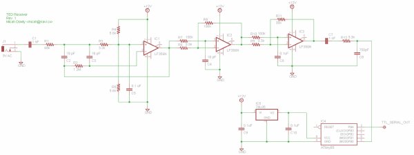
In fact a reasonably useful example will be given using a 68HC705J1A single chip microcontroller. We will get it to read the data from the keyboard, convert the scan codes into ASCII and send it out in RS-232 format at 9600 BPS. However we won’t stop here, you will want to see the bi-directional use of the KBD Clock & Data lines, thus we will use the keyboards status LEDS, Num Lock, Caps Lock and Scroll Lock.

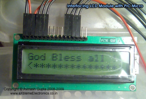
This can be used for quite a wide range of things. Teamed up with a reasonably sized 4 line x 40 character LCD panel, you could have yourself a little portable terminal. Or you could use it with a microcontroller development system. The 68HC705J1A in a One Time Programmable (OTP) is only a fraction of the cost of a 74C922 keyboard decoder chip, which only decodes a 4 x 4 matrix keypad to binary.

The keyboard doesn’t need to be expensive either. Most people have many old keyboards floating around the place. If it’s an AT Keyboard, then use it (XT keyboards will not work with this program.) If we ever see the introduction of USB keyboards, then there could be many redundant AT keyboards just waiting for you to hook them up.
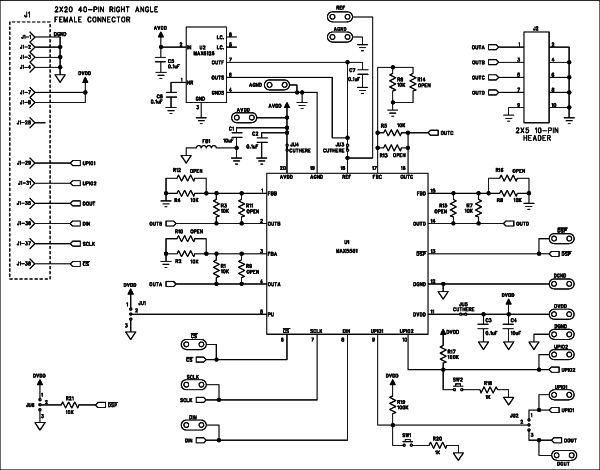
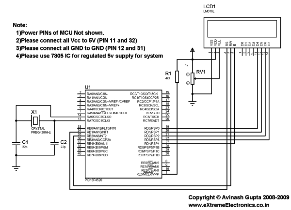
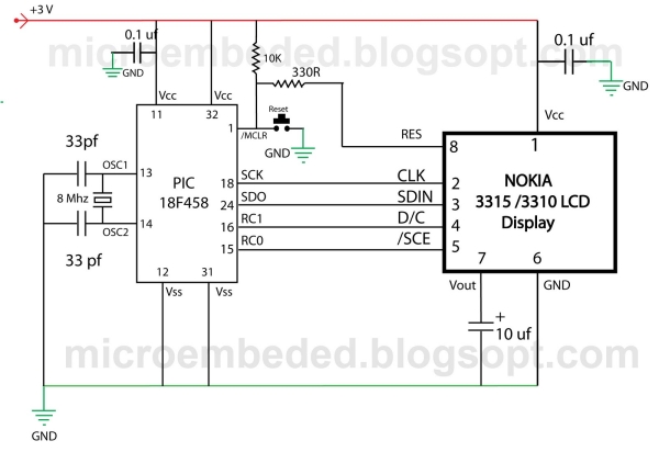
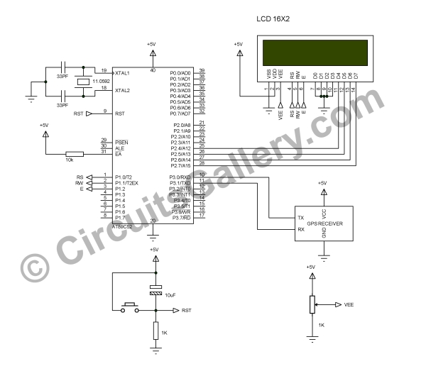
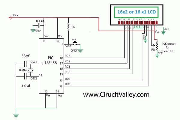
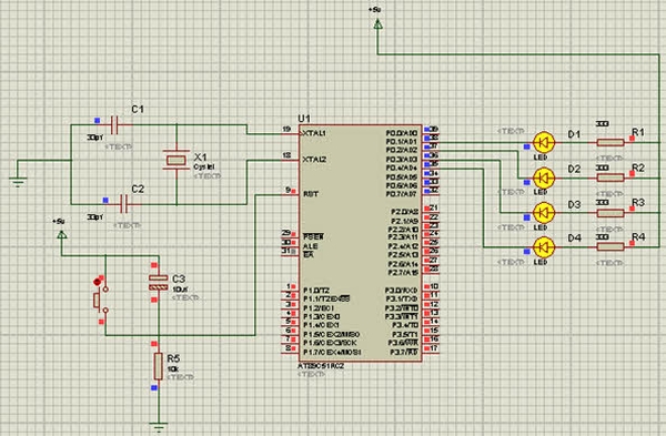
Interfacing the AT keyboard. SchematicFeatures

Before we start with the technical aspects of the project, the salesman in me wants to tell you about the features packed into the 998 bytes of code.

  • Use of the keyboard’s bi-directional protocol allowing the status of the Num Lock, Caps Lock and Scroll Lock to be displayed on the Keyboards LEDs.
  • External Reset Line activated by ALT-CTRL-DEL. If you are using it with a Microcontroler development system, you can reset the MCU with the keyboard. I’ve always wanted to be able to use the three fingered solute on the HC11!
  • Scroll Lock and Num Lock toggles two Parallel Port Pins on the HC705. This can be used to turn things on or off, Select Memory Pages, Operating Systems etc
  • “ALTDEC” or what I call the Direct Decimal Enter Routine. Just like using a PC, when you enter a decimal number when holding down one of the ALT keys the number is sent as binary to the target system. E.g. If you press and hold down ALT, then type in 255 and release ALT, the value FF (Hex) will be sent to the system. Note. Unlike the PC, you can use both the numeric keypad or the numbers along the top of the keyboard.
  • “CTRLHEX” or you guessed it, Direct Hexadecimal Enter Routine. This function is not found with the PC. If you hold CTRL down, you can enter a Hexadecimal number. Just the thing for Development Systems or even debugging RS-232 Comms?
  • Output is in ASCII using a RS-232 format at 9600 BPS. If using it with a development System, you can tap it in after the RS-232 Line Transceivers to save you a few dollars on RS-232 Level Converters.


For more detail: Interfacing the AT keyboard.

Current Project / Post can also be found using:

  • pic microcontroller usb keyboard

The post Interfacing the AT keyboard. appeared first on PIC Microcontroller.

Interfacing LCD Modules with PIC Microcontrollers.

$
0
0

A large number of embedded project require some type of user interface. This includes displaying numerical, textual and graphical data to user. For very simple numerical display we can use 7 segment displays. If the requirement is little more than that, like displaying some alphanumeric text, we can use LCD Modules. They are cheap enough to be used in low cost projects. They come in various sizes for different requirement. A very popular one is 16×2 model. It can display 2 lines of 16 characters. Other models are 16×4,20×4, 8×1,8×2 etc.

In this tutorial we will learn how we can use such modules with Microchip PIC Microcontrollers. Here I will present my LCD library which you can use to create LCD based application/projects quickly. For demo I will use PIC18F4520 Microcontroller but you can use any PIC18 MCU. But you have to calculate the CONFIG values for correct setting and CPU clock selection etc. That means the chip should be configured correctly. See datasheet for more info on CONFIG bytes.

Interfacing LCD Modules with PIC Microcontrollers. MPLAB Project Creation

First create a MPLAB project as described in this tutorial. Name the project LCD. Also add a main file called “lcd_test.c”. To use my LCD library you need to add it to your project. Just copy/paste the following files to your project folder.

Header Files

  • lcd.h
  • myutils.h

Source File

  • lcd.c

How to add files to MPLAB Project is described here.

Now you are ready to the library functions to interact with the LCD module.

Interfacing LCD Modules with PIC Microcontrollers SchematicSample Program (lcd_test.c)

/********************************************************************

16X2 ALPHANEUMERIC LCD INTERFACING LIBRARY TEST PROGRAM

---------------------------------------------------------

A testing program for our LCD library.

Easy to use library for interfacing 16x2 lcd in 4 bit mode.
MCU: PIC18FXXXX Series from Microchip.
Compiler: HI-TECH C Compiler for PIC18 MCUs (http://www.htsoft.com/)

Copyrights 2008-2009 Avinash Gupta
eXtreme Electronics, India

For More Info visit
http://www.eXtremeElectronics.co.in

Mail: me@avinashgupta.com

********************************************************************/
#include <htc.h>

#include "lcd.h"

//Chip Settings
__CONFIG(1,0x0200);
__CONFIG(2,0X1E1F);
__CONFIG(3,0X8100);
__CONFIG(4,0X00C1);
__CONFIG(5,0XC00F);
//Simple Delay Routine
void Wait(unsigned int delay)
{   for(;delay;delay--)      __delay_us(100);}void main()
{   //Let the Module start up   Wait(100);   //Initialize the LCD Module
   LCDInit(LS_BLINK);   //Clear the Module
   LCDClear();   //Write a string at current cursor pos
   LCDWriteString("Good Is Great !!");

   Wait(20000);   //Now Clear the display
   LCDClear();   LCDWriteString("God Bless all !!");
   //Goto POS (X=0,Y=1 i.e. Line 2)
   //And Write a string
   LCDWriteStringXY(0,1,"<**************>");
   Wait(20000);   //Write Some Numbers
   for(char i=0;i<100;i++)
   {         LCDClear();  LCDWriteInt(i,3); Wait(3000);   }
   LCDClear();   LCDWriteString("    The  End    ");
   //Loop Forever   while(1);}


For more detail: Interfacing LCD Modules with PIC Microcontrollers. 

The post Interfacing LCD Modules with PIC Microcontrollers. appeared first on PIC Microcontroller.


Interfacing Ultrasonic Distance Sensor : ASCII Output with PIC Microcontroller

$
0
0

In some of our projects, we may want to measure the distance of an object from a point. Ultrasonic Distance Sensors are the best sensor which provides stable, accurate, precise, non-contact distance measurements from 2cm to 4m. Ultrasonic Sensors can be used to measure distance between moving or stationary objects. Being very accurate and stable, these devices find large number of applications in robotics fields. For example it can be used as an excellent replacement for IR sensors in  a Micromouse. In this tutorial we will lean to interface an Ultrasonic Distance Sensor with PIC Microcontroller.

Interfacing Ultrasonic Distance Sensor  ASCII Output with PIC MicrocontrollerHere for demonstration we are using Rhydolabz Ultrasonic Distance Sensor with ASCII Output. It can be easily interfaced with a PIC Microcontroller using USART by just connecting the output pin of the sensor to RX pin of the microcontroller. In every 500ms this sensor transmits an ultrasonic burst and listens for its echo. The sensor sends out ASCII value corresponds to the time required for the ultrasonic burst to return to the sensor. The UART of the sensor is operates at a baud rate 9600 and the sensor can be powered by  a 5V DC Supply. The ASCII output of the sensor will be equal to the distance to the obstacle in centimeter (cm).

Interfacing Ultrasonic Distance Sensor  ASCII Output with PIC Microcontroller SchematicThe sensor has three pins…

  • Vcc  – +5V DC Supply to the Sensor
  • GND –  Ground Level of the Power Supply
  • SIG – Signal, Serial Data Out’


For more detail: Interfacing Ultrasonic Distance Sensor  ASCII Output with PIC Microcontroller

The post Interfacing Ultrasonic Distance Sensor : ASCII Output with PIC Microcontroller appeared first on PIC Microcontroller.

Nokia 3315 / 3310 LCD interfacing with Microcontroller

$
0
0

Displaying content on a normal alphanumeric display is very limited ,we have to be limited with the font size and we can’t draw any graphics also. but convention Graphics lcd are really very expensive so here is the solution, you can use Nokia 3315 / 3310 monochrome  LCD to display your large font text and graphics . the reason behind using this LCD is ,it is really very cheap and can be powered with 3 volts supply. so it is really good for battery powered application.

Project Description 

however you can use almost any microcontroller (with capability to work on 3v ) do display content on this LCD, may be that micro controller is PIC , AVR or MSP 430 , but in this demonstration we will be using Microchip PIC 18F458 Microcontroller.
Nokia 3315 3310 LCD interfacing with MicrocontrollerThe software program for this project will be written in C with MPLAB IDE , This LCD has a resolution of 84×48 pixel.

About LCD:-

Nokia 3315 / 3310 Graphical LCD uses PCD8544 Controller chip From Philips. It is a chip-on glass(COG) with  8 pin connector on the back side of the LCD . You can refer to its datasheet for more information about this controller. (CLICK HERE TO DOWNLOAD PCD8544 Controller DATA SHEET).we will discuss only few main points here for out project purpose.

The typical example of RAM is shown in the figure blow, The vertical axes area addressed form 0 to 5 with eight bits for each address when combining with x axes, it can be represented as bank.

The horizontal axes are addressed form 0 to 83 and each bit will refer the corresponding pixel in X direction.

Addressing Mode  
There are two type of addressing mode in this LCD
Vertical addressing Mode

A byte is sent to The LCD as follows:-
1:- Set SCE To GND
2.Set D/C to required state (Data or command)
3.Place a bit in SDIN line
4. Make high-to-low transition in CLK input.
5.Repeat step 3 and 4 for the remaining seven bits.

Nokia 3315 3310 LCD interfacing with Microcontroller Schematic

The initialization sequence of  LCD

1. Pull SCE line to Ground to Enable The LCD.
2 Set D/C pin low to send commands to the LCD.
3. Write 0x21 Byte to LCD on the serial Bus. Here the LCD operates in Function set Command For extended instruction set.
4. Write 0xC8 Byte to LCD on the serial Bus. This set the operating voltage (Vop) of the LCD.
  5. Write 0x06 Byte to LCD on the serial Bus. This set the temperature coeffcient.
  6.  Write 0x13 Byte To LCD on the serial Bus.  This set the bias system of the LCD. 
7.  Write 0x20 Byte To LCD on the serial Bus.  This allow the LCD to operate in function set command with basic instruction.


For more detail: Nokia 3315 3310 LCD interfacing with Microcontroller

Current Project / Post can also be found using:

  • serial interfacing lcd pic microcontroller
  • lcd on project
  • microcontroller phone interface
  • microcontroller projects with lcd

The post Nokia 3315 / 3310 LCD interfacing with Microcontroller appeared first on PIC Microcontroller.

Interfacing EM-18 RFID Module with PIC Microcontroller

$
0
0

EM-18 RFID Reader Module is the one the most commonly used module for Radio Frequency Identification Projects. It features Low Cost, Small Size, Low Power Consumption and Easy to use. It can be directly interfaced with microcontrollers using UART communication. Software UART can be used for microcontrollers having no UART modules. In this tutorial we will see How to Interface EM-18 RFID Reader Module with PIC 16F877A Microcontroller. By understanding the basic idea, you will be able to interface it with any microcontrollers.

Interfacing EM-18 RFID Module with PIC MicrocontrollerWorking

The EM-18 RFID Reader module generates and radiates RF Carrier Signals of frequency 125KHz through its coils. When a 125KHz Passive RFID Tag (have no battery) is brought in to this field, will get energized from it. These RFID Tags are usually made using a CMOS IC EM4102. It gets enough power and master clock for its operations from the electromagnetic fields produced by RFID Reader.

By changing the modulation current through the coils, tag will send back the information contained in the factory programmed memory array.

Interfacing with PIC Microcontroller

EM-18 RFID Reader Module can be directly interfaced with 5V PIC Microcontrollers using UART module. For 3.3V deviced you need to add additional voltage divider resistors to reduce 5V to 3.3V. You may also use Software UART if a dedicated UART module is not available.

Interfacing EM-18 RFID Module with PIC Microcontroller SchematicWhen a RFID Tag is bring in to the field of EM-18 RFID Reader, it will read its tag number and give output via TX terminal. The BEEP terminal will become LOW to indicate valid tag detection. The UART output will be 12 ASCII data, among these first 10 will be tag number and last 2 will be XOR result of the tag number which can be used for error testing.

For eg : If the RFID tag number is 500097892E, output of EM-18 Reader will be 500097892E60 where 60 is 50 xor 00 xor 97 xor 89 xor 2E.


For more detail: Interfacing EM-18 RFID Module with PIC Microcontroller

The post Interfacing EM-18 RFID Module with PIC Microcontroller appeared first on PIC Microcontroller.

PIC16F84A LCD interfacing code (In 4bit mode) and Proteus simulation

$
0
0

This post provides the LCD[1] interfacing code in 4bit mode using PIC16F84A microcontroller. This code is written in C language using MPLAB with HI-TECH C compiler. You can download this code from the ‘Downloads‘ section at the bottom of this page.

PIC16F84A LCD interfacing 4bit mode

It is assumed that you know how to make an LED blink with PIC16F84A microcontroller. If you don’t then please read this page first, before proceeding with this article.

LCD interfacing circuit in 4bit mode with PIC16F84A is shown below.

In the above figure, RA0 pin is being used as Enable pin for LCD. RA1 pin is used as RS pin and RB4 to RB7 pins are being used as Data bus for the LCD. When code starts runing then Hello is displayed on the LCD.

Any 16×2 LCD can be used here which has HD44780U controller in it. For example, JHD162A LCD can be used with this code easily.


Code

The code for the main function is shown below.

In the main function, firstly LCD is initialized using InitLCD() function. After that, “Hello” is written on the LCD screen[2]. In this way using WriteDataToLCD() function, you can write any character on the LCD screen.

PIC16F84A LCD interfacing 4bit mode schematic

InitLCD() function initializes the LCD[3] by giving the initializing commands required to turn the LCD on. This function is shown below.

Downloads

LCD interfacing code in 4bit mode using PIC16F84A was compiled in MPLAB v8.85 with HI-TECH C v9.83 compiler and simulation was made in Proteus v7.10. To download code and Proteus simulation click here.


For more detail: PIC16F84A LCD interfacing code (In 4bit mode) and Proteus simulation

The post PIC16F84A LCD interfacing code (In 4bit mode) and Proteus simulation appeared first on PIC Microcontroller.

Lab 4: Interfacing a character LCD using PIC16F688

$
0
0

Description

HD44780 based LCD displays are very popular among hobbyists because they are cheap and they can display characters. Besides they are very easy to interface with microcontrollers and most of the present day high-level compilers have in-built library routines for them. Today, we will see how to interface an HD44780 based character LCD to a PIC16F688 microcontroller. The interface requires 6 I/O lines of the PIC16F688 microcontroller: 4 data lines and 2 control lines. A blinking test message, “Welcome to Embedded-Lab.com”, will be displayed on the LCD screen.

character LCD

Required Theory

All HD44780 based character LCD displays are connected through 14 pins: 8 data pins (D0-D7), 3 control pins (RS, E, R/W), and three power lines (Vdd, Vss, Vee). Some LCDs have LED backlight feature that helps to read the data on the display during low illumination conditions. So they have two additional connections (LED+ and LED-), making altogether 16 pin. A 16-pin LCD module with its pin diagraam is shown below.

Control pins
The control pin RS determines if the data transfer between the LCD module and an external microcontroller are actual character data or command/status. When the microcontroller needs to send commands to LCD or to read the LCD status, it must be pulled low. Similarly, this must be pulled high if character data is to be sent to and from the LCD module.

The direction of data transfer is controlled by the R/W pin. If it is pulled Low, the commands or character data is written to the LCD module. And, when it is pulled high, the character data or status information from the LCD registers is read. Here, we will use one way data transfer, i.e., from microcontroller to LCD module, so the R/W pin will be grounded permanently.

The enable pin (E) initiates the actual data transfer. When writing to the LCD display, the data is transferred only on the high to low transition of the E pin.

Power supply pins
Although most of the LCD module data sheets recommend +5V d.c. supply for operation, some LCDs may work well for a wider range (3.0 to 5.5 V). The Vdd pin should be connected to the positive power supply and Vss to ground. Pin 3 is Vee, which is used to adjust the contrast of the display. In most of the cases, this pin is connected to a voltage between 0 and 2V by using a preset potentiometer.

Data pins
Pins 7 to 14 are data lines (D0-D7). Data transfer to and from the display can be achieved either in 8-bit or 4-bit mode. The 8-bit mode uses all eight data lines to transfer a byte, whereas, in a 4-bit mode, a byte is transferred as two 4-bit nibbles. In the later case, only the upper 4 data lines (D4-D7) are used. This technique is beneficial as this saves 4 input/output pins of microcontroller. We will use the 4-bit mode.

For further details on LCDs, I recommend to read these two articles first from Everyday Practical Electronics magazine : How to use intelligent LCDs Part 1, and Part 2.

Circuit Diagram

Data transfer between the MCU and the LCD module will occur in the 4-bit mode. The R/W pin (5) of the LCD module is permanently grounded as there won’t be any data read from the LCD module. RC0-RC3 serves the 4-bit data lines (D4-D7, pins 11-14) of the LCD module. Control lines, RS and E, are connected to RC4 and RC5. Thus, altogether 6 I/O pins of the PIC16F688 microcontrollers are used by the LCD module. The contrast adjustment is done with a 5K potentiometer as shown below. If your LCD module has backlight LED, use a 68Ω resistance in series with the pin 15 or 16 to limit the current through the LED. The detail of the circuit diagram is shown below.


For more detail: Lab 4: Interfacing a character LCD using PIC16F688

The post Lab 4: Interfacing a character LCD using PIC16F688 appeared first on PIC Microcontroller.

Interfacing GPS Receiver with 8051 Microcontroller -AT89C52

$
0
0

How to interface GPS receiver with 8051 (AT89C52)? GPS receiver is an electronics device capable of receiving Global Positioning System (GPS) signals to decide the device’s location on Earth. Today GPS receiver is popular in vehicles and other navigation equipment. As we know that GPS is free to use there is no subscription charge for that. Consider if you did interface GPS receiver with 8051! You can explore with GPS systems as you like. So here I’m introducing GPS interface with microcontroller circuit. This article focused on GPS interfacing with microcontroller and LCD (16×2).

Interfacing GPS Receiver with 8051 Microcontroller -AT89C52LCD is used to display the latitude and longitude, it will continually update the GPS data, and I have used KEIL compiler to program 89C51 in Embedded C. UART in 89C51 is used here to connect GPS with Microcontroller. This GPS interfacing with microcontrollers embedded design by interactive simulation tutorial will be a stepping stone to GPS interface engineering project kits. We understands the importance of program source code for Engineering students thus provided interfacing GPS receiver with 8051 C code compiled in Keil IDE.

What is GPS?

  • Just before gonna to interfacing GPS receiver with 8051 program it is better to know what is GPS?
  • GPS, stands for Global Positioning System (GPS), is a satellite established navigation scheme built with a network of 24 satellites + 3 backup satellite positioned into orbit by the U.S. Department of Defense.
  • At the beginning stage GPS were aimed for military operations only. Though in the 1980s, the U.S. government resolved to permit the GPS program to be used by common people like us.
  • Climate situations do not disturb the capability for GPS signals. GPS system works 24/7 everywhere in the Earth. There are no subscription fees or setup charges to use GPS.

Components required for interfacing GSM receiver to 89C51

  1. AT89C52
  2. Crystal (11.059MHz)
  3. Capacitor (33PF, 10µF)
  4. Resistor (10KΩ, 1KΩ)
  5. POT (10KΩ)
  6. LCD (16×2)
  7. GPS receiver

Interfacing GPS Receiver with 8051 Microcontroller -AT89C52 SchematicHow To Interface GPS with 8051 Microcontroller (At89c52)

  • The core component is 89C51 microcontroller which drives the LCD module to display data obtained from GPS receiver.
  • GPS receiver frequently send information contain a number of data such as Global positioning system fixed data (GGA), Geographic position-latitude/longitude(GLL), GNSS DOP and active satellites(GSA), GNSS satellites in view(GSV), Recommended minimum specific GNSS data(RMC), Course over ground and ground speed(VTG), Date and Time (ZDA), Datum reference (DTM).


For more detail: Interfacing GPS Receiver with 8051 Microcontroller -AT89C52

The post Interfacing GPS Receiver with 8051 Microcontroller -AT89C52 appeared first on PIC Microcontroller.

DC Motor Interfacing With PIC Microcontroller Using L293 Motor Driver IC

$
0
0

L293d is an H Bridge bidirectional motor driver IC used to interface DC motor and stepper motors to Microcontrollers.

CircuitsGallery.com already discussed about the working principle of L293 IC with an example of bidirectional motor driver circuit.It is very easy to make a DC motor control using microcontroller. In this article I’m gonna show you the interfacing of DC motor with PIC16F877A microcontroller using L293D motor driver with the help of Mikro C coding and Proteus 8 simulation. Basically it is a bidirectional motor driver circuit with PIC MCU.This is the most common circuit in robotics engineering. I’m sure this article will be helpful for PIC MCU beginners.

DC Motor Interfacing With PIC Microcontroller Using L293 Motor Driver ICWhat is H Bridge?

H bridges are widely discussed topic in electronics. As we know, just changing the polarity of supply voltage causes rotating of DC motor in reverse direction.

But this method is not suitable for practical circuit. So, how to run DC motor in clockwise and anti-clockwise direction without changing the supply polarity?

Here comes the importance of H Bridge. In a typical H Bridge circuit two pairs of transistors are connected in a bridge fashion and the motor is driven through the collector terminal.

Read more: H Bridge motor driver circuit using transistors

DC Motor Interfacing With PIC Microcontroller Using L293 Motor Driver IC SchematicWhy L293?

Obviously we know that ICs make life easy!

  • The transistor based H bridges are little complex and bulky and also time consuming while implementing practically.
  • L293 is basically an H bridge IC capable of driving two motors simultaneously, that means it has two embedded H bridges inside!

Interfacing of L293 to DC motor and microcontroller is very easy and simple process.

The specialty of L293 is that it has dedicated ‘Enable Pin’ to control the motor. By manipulating this pin it is possible to control the speed of dc motor with Pulse Width Modulation technology.


For more detail: DC Motor Interfacing With PIC Microcontroller Using L293 Motor Driver IC

Current Project / Post can also be found using:

  • interfacing of DC motor to the PIC controller

The post DC Motor Interfacing With PIC Microcontroller Using L293 Motor Driver IC appeared first on PIC Microcontroller.


Interfacing Relay to Microcontroller

$
0
0

Figure 1 shows the basic relay driver circuit. As you can see an NPN transistor BC547 is being used to control the relay. The transistor is driven into saturation (turned ON) when a LOGIC 1 is written on the PORT PIN thus turning ON the relay. The relay is turned OFF by writing LOGIC 0 on the port pin. A diode (1N4007/1N4148) is connected across the relay coil; this is done so as to protect the transistor from damage due to the BACK EMF generated in the relay’s inductive coil when the transistor is turned OFF. When the transistor is switched OFF the energy stored in the inductor is dissipated through the diode & the internal resistance of the relay coil. Normally 1N4148 can be used as it is fast switching diode with a maximum forward current of 300ma. This diode is also called as free-wheeling diode.

Interfacing Relay to Microcontroller SchematicThe LED is used to indicate that the RELAY has been turned ON. The resistor R1 defines the current flowing through the LED thereby defining the LED’s intensity.

Resistor R2 is used as a Series Base Resistor to set the base current. When working with 8051 controllers I have noted that it’s not compulsory to use this resistor as the controller has internal 10k resistor which acts as a base resistor.

Microcontrollers have internal pull up resistors hence when a port pin is HIGH the output current flows through this internal pull up resistor. 8051 microcontrollers have an internal pull up of 10KΩ. Hence the maximum output current will be  5v/10k = 0.5ma. This current is not sufficient to drive the transistor into saturation and turn ON the relay. Hence an external pull up resistor R3 is used. Let us now calculate the value of R3.

Interfacing Relay to Microcontroller SchematicNormally a relay requires a pull in current of 70ma to be turned ON. So our BC547 transistor will require enough base current to make sure it remains saturated and provide the necessary collector current i.e. 70ma. The gain (hfe) of BC547 is 100 so we need to provide at least   70ma/100 = 0.7ma  of base current. In practice you require roughly double the value of this current so we will calculate for 1.4ma of base current.


For more detail: Interfacing Relay to Microcontroller Schematic

Current Project / Post can also be found using:

  • I2C to USB pic
  • Proteus I2C simulation steps using pic18f

The post Interfacing Relay to Microcontroller appeared first on PIC Microcontroller.

Lecture 43 : Interfacing PIC16F877 Microcontroller with an LCD

$
0
0
Aim

To interface LCD (Displaytech 162A) with PIC16F877microcontroller and to display “IITK” in the Liquid Crystal Display (LCD).

Components/Softwares
  1. MPLAB IDE (PIC microcontrollers simulator)
  2. PIC BURNER 3 with software to load the code
  3. LCD (Displaytech 162A)
  4. Computer System with Windows operating system and RS 232 cable
  5. PIC16F877 Microcontroller

Lecture 43  Interfacing PIC16F877 Microcontroller with an LCD

  1. +5V D.C Power Supply
  2. Resistors – 10K Ω-1,50Ω-1
  3. Capacitors – 27 µ F-2
  4. Potentiometers – 10K Ω -1
  5. 20MHz Crystal oscillator
  6. SPST switches -1
Procedure
  1. Write the assembly code in MPLAB IDE simulator , compile it and check for errors
  2. Once the code was error free, run it and check the output in the simulator.
  3. After checking the code in the simulator, load the code (in .HEX format) into PIC16F877 microcontroller using PIC BURNER3.
  4. Make connections as shown in the circuit diagram.
  5. Switch on the power supply and observe “IITK” displayed in the LCD.

Liquid Crystal Display (LCD-Displaytech 162A )LCD Displaytech 162A consists of a LCD panel, a controller IC (KS0070B) and a back light LED. The LCD module consists of total 16 pins in which, 2 are for power supply, 2 pins for Backlight LED, one pin for contrast adjustment, 3 pins are for control signals and 8 pins are data pins. In order to display any data, we need to do certain initiations. The following are the main three steps in displaying any data in the LCD display.

Lecture 43  Interfacing PIC16F877 Microcontroller with an LCD Schematic

  1. Initializing LCD by sequence of instructions
  2. Executing commands depending on our settings in the LCD
  3. Writing data into the DRAM locations of LCD in the Standard Character Pattern of LCD

For doing above steps, refer the manual for LCD and follow the instructions and timing diagrams strictly.
MPLABIDEMPLABIDE is a free software which can be downloaded from the website www.microchip.com
Working with MPLABIDE :
MPLABIDE is a simulator for PIC microcontrollers to write and edit the code in assembly language, compile it and also to run the code. Output can be verified using simulator.


For more detail: Lecture 43  Interfacing PIC16F877 Microcontroller with an LCD

The post Lecture 43 : Interfacing PIC16F877 Microcontroller with an LCD appeared first on PIC Microcontroller.

HD44780 16×2 Char LCD Interfacing with microcontroller

$
0
0

Project Description:-

In this project we are going to learn various things about this chip set and displaying text on this LCD. The HD44780 16×2 char LCD screen Use 8bit and 4 bit parallel interface with backlight.

This Primary Objective in this project are:-

1.  Displaying  “Hello Word!! LCD ” message on the scree.
2.   Interfacing The LCD to the Microcontroller Using 8bit  Mode and 4 Bit Mode.
3.  Generating and Displaying Custom Char on the LCD Screen. clik here for custom char

Operation 

as i have mentioned  before this type of lcd are connected to microcontroller using parallel 8bit or 4bit lines.
using 8 bit method is quite simple but take 8 lines (for data or command)+ 3 control signal total 11 line , i guess few small microcontrollers don’t even have that much of I/O lines ,so in 4 bit mode total 7 lines (sometimes 6 ) are required .  in this tutorial i will show you with both of the methods .

HD44780 16x2 Char LCD Interfacing with microcontroller Pin description

PIN NUMBER SYMBOL FUNCTION
1 Vss GND
2 Vdd  + 3V or + 5V
3 Vo Contrast Adjustment
4  RS H/L Register Select Signal
5 R/W H/L Read/Write Signal
6 E  H → L Enable Signal
7  DB0 H/L Data Bus Line
8  DB1 H/L Data Bus Line
9  DB2 H/L Data Bus Line
10  DB3 H/L Data Bus Line
11  DB4 H/L Data Bus Line
12  DB5 H/L Data Bus Line
13  DB6 H/L Data Bus Line
14  DB7 H/L Data Bus Line
15 A/Vee + 3.5V for LED/Negative Voltage Output
16 K K Power Supply for B/L (OV)

in 8 bit mode all the Data line DB0 to DB7 are being used for transferring the the data to lcd but in 4-bit mode only 4 line form DB4 to DB7 are being used to transfer the  8 bit wide data in two peaces one after another .

we can’t display any data on the lcd until all the required internal command register of the lcd are not being properly initialized.
to know every thing about this lcd controller .. you can go through it’s data sheet
click here to download HD44780 data sheet
so now we will learn how to initialize the lcd.

LCD Commands

Clear Display

clear  and place the cursor in the first position (address 0). The bit I / D to 1 by default.

RS R / W DB7 DB6 DB5 DB4 DB3 DB2 DB1 DB0
0 0 0 0 0 0 0 0 0 1

Return the cursor to Home

Place the cursor in the home position (address 0) and make the display starts to move from its original position. The contents of the RAM display data (DD RAM) remains unchanged. The address of the RAM for display data (DD RAM) is set to 0.

RS R / W DB7 DB6 DB5 DB4 DB3 DB2 DB1 DB0
0 0 0 0 0 0 0 0 1 X

Entry Mode in Set

Set cursor moving direction and specify that the display moves to the next position of the screen or not. These operations are performed during reading or writing of the DD RAM or CG RAM. To view usually set bit S = 0.

RS R / W DB7 DB6 DB5 DB4 DB3 DB2 DB1 DB0
0 0 0 0 0 0 0 1 I / D S

Display ON / OFF Control

Turn on or off by turning ON / OFF both the LCD (D) as the cursor (C) and whether or not this last flash (B).

RS R / W DB7 DB6 DB5 DB4 DB3 DB2 DB1 DB0
0 0 0 0 0 0 1 D C B

Cursor or Display Shift

Move the cursor to move the LCD without changing the memory contents of the display data DD RAM.

RS R / W DB7 DB6 DB5 DB4 DB3 DB2 DB1 DB0
0 0 0 0 0 1 S / C R / L X X

HD44780 16x2 Char LCD Interfacing with microcontroller SchematicFunction Set

Set the size of interface with the data bus (DL), number of lines in the LCD (N) and character type (F).

RS R / W DB7 DB6 DB5 DB4 DB3 DB2 DB1 DB0
0 0 0 0 1 DL N F X X

Set the CG RAM Address

The LCD module defined in addition to all the ASCII character set allows the user to define 4 or 8 characters. The composition of these characters is saved to a CG RAM memory called up to 64 bytes. Each user defined character consists of 16 or 8 bytes that are stored in successive positions of the CG RAM.

Using this instruction sets the CG RAM memory address from which the bytes will be stored that define a character. Running this command all the data that is subsequently read or write this memory made from CG RAM.


For more detail: HD44780 16×2 Char LCD Interfacing with microcontroller 

Current Project / Post can also be found using:

  • pic24f i2c master with usb example

The post HD44780 16×2 Char LCD Interfacing with microcontroller appeared first on PIC Microcontroller.

Interfacing 7-Segment Display With PIC Microcontroller – MikroC

$
0
0

The 7-segment display is the earliest type of an electronic display that uses 7 LEDs bars arranged in a way that can be used show the numbers 0 – 9. (actually 8 segments if you count the decimal point, but the generic name adopted is 7-segment display.) These devices are commonly used in digital clocks, electronic meters, counters, signalling, and other equipment for displaying numeric only data. 

Interfacing 7-Segment Display With PIC Microcontroller - MikroCIt is not different from an LED in terms of interfacing, by turning the appropriate segments ON and OFF we can display easily the numbers 0 to 9 and optionally the decimal point (DP). 

The segments of the displays are normally referred to by letters ‘a’ to ‘g’.
Figures 2 and 3 show how a 7-segment display can display digits. 
In figure 2, all the segments (LEDs) are switched on to display the digit “8” with the decimal point. On the other hand, in figure 3, segments a, b, c, d and g are switched on to display the digit “3”.  any combination can be used to display any desired digit.
The segments can also be used to display some letters, but this is limited. For example, the letter “b” can be displayed by switching on the segments  c, d, e and f and the letter “F” by switching on segments a, e, f and g.

In figure 4, the anode pins of all the segments are connected together and this pin is usually connected to the power supply. Individual segments are turned ON by grounding the required segment pin through the microcontroller by sending a “0” to the pin output. 
In figure 5 as well as in figure 1, all the cathodes of all the segments are connected together and this pin is usually connected to ground. Individual segments are turned ON by applying voltage to the required segment pin through the microcontroller by sending a “1” to the pin output. 

A PIC can source or sink 25mA of current per Input/Output pin. When designing an LED circuit, we have to know the typical voltage drop as we have learnt from the Blinking an LED Connected to a PIC microcontroller article. 
As with standard LEDs, it is required to use current limiting resistors in each segment of the display to limit the current as shown in figure 1. 
Interfacing 7-Segment Display With PIC Microcontroller - MikroC SchematicThe easiest way to display a number on the 7-segment is to find a way to determine or look up the pattern corresponding to the digit to be displayed . This can be something like a table showing the numbers and the corresponding segment that should be turned ON or OFF to display something and the required number (this can be in decimal, hexadecimal or in binary format) to be sent to the port where the display is connected to in order to display a specific number.


For more detail: Interfacing 7-Segment Display With PIC Microcontroller – MikroC

The post Interfacing 7-Segment Display With PIC Microcontroller – MikroC appeared first on PIC Microcontroller.

Major Electronic Peripherals Interfacing to Microcontroller 8051

$
0
0

Interfacing is one of the important concepts in microcontroller 8051 because the microcontroller is a CPU that can perform some operation on a data and gives the output. However to perform the operation we need an input device to enter the data and in turn output device displays the results of the operation. Here we are using keyboard and LCD display as input and output devices along with the microcontroller.

Interfacing is the process of connecting devices together so that they can exchange the information and that proves to be easier to write the programs. There are different type of input and output devices as for our requirement such as LEDs, LCDs, 7segment, keypad, motors and other devices.

Here is given some important modules interfaced with microcontroller 8051.

Major Electronic Peripherals Interfacing to Microcontroller 80511. LED Interfacing to Microcontroller:

Description:

LEDs are most commonly used in many applications for indicating the output. They find huge range of applications as indicators during test to check the validity of results at different stages. They are very cheap and easily available in a variety of shape, color and size.

The principle of operation of LEDs is very easy. A simple LEDs also servers as a basic display devices, it On and OFF state express meaning full information about a device. The common available LEDs have a 1.7v voltage drop that means when we apply above 1.7V, the diode conducts. The diode needs 10mA current to glow with full intensity.

The following circuit describes “how to glow the LEDs”.

LEDs can be interfaced to the microcontroller in either common anode or common cathode configuration. Here the LEDs are connected in common anode configuration because the common cathode configuration consumes more power.

Source code:

#include<reg51.h>
void main()
{
unsigned int i;
while(1)
{
P0=0x00;
for(i=0;i<30000;i++);
P0=0xff;
for(i=0;i<30000;i++);}}

2. 7-Segment Display interfacing circuit

Description:
A Seven segment display is the most basic electronic display. It consists of eight LEDs which are associated in a sequence manner so as to display digits from 0 to 9 when proper combinations of LEDs are switched on. A 7-segment display uses seven LEDs to display digits from 0 to 9 and the 8th LED is used for dot.

The 7-segment displays are used in a number of systems to display the numeric information. They can display one digit at a time. Thus the number of segments used depends on the number of digits to display. Here the digits 0 to 9 are displayed continuously at a predefined time delay.

The 7-segment displays are available in two configurations which are common anode and common cathode. Here common anode configuration is used because output current of the microcontroller is not sufficient enough to drive the LEDs. The 7-segment display works on negative logic, we have to provide logic 0 to the corresponding pin to make on LED glow.

Source Code:

#include<reg51.h>
sbit a= P3^0;
void main()
{
unsigned char n[10]= {0x40,0xF9,0x24,0x30,0x19,0x12,0x02,0xF8,0xE00,0x10};
unsigned int i,j;
a=1;
while(1)
{
for(i=0;i<10;i++)
{
P2=n[i];
for(j=0;j<60000;j++);
}
}
}

3. LCD Interfacing to Microcontroller

LCD stands for liquid crystal display which can display the characters per line. Here 16 by 2 LCD display can display 16 characters per line and there are 2 lines. In this LCD each character is displayed in 5*7 pixel matrix.

LCD is very important device which is used for almost all automated devices such as washing machines, an autonomous robot, power control systems and other devices. This is achieved by displaying their status on small display modules like 7-seven segment displays, multi segment LEDs etc. The reasons being, LCDs are reasonably priced, easily programmable and they have a no limitations of displaying special characters.

It consists of two registers such as command/instruction register and data register.

The command/instruction register stores the command instructions given to the LCD. A command is an instruction which is given to the LCD that perform a set of predefined tasks like initializing, clearing the screen, setting the cursor posing, controlling display etc.

The data register stores the data to be displayed on LCD. The data is an ASCII value of the characters to be displayed on the LCD.

Operation of LCD is controlled by two commands. When RS=0, R/W=1 it reads the data and when RS=1, R/W=0, it writes (print) the data.

Source code:

#include<reg51.h>
#define kam P0

sbit rs= P2^0;
sbit rw= P2^1;
sbit en= P2^2;

Major Electronic Peripherals Interfacing to Microcontroller 8051 Schematicvoid lcd_initi();
void lcd_dat(unsigned char );
void lcd_cmd (unsigned char );
void delay(unsigned int );
void display(unsigned char *s, unsigned char r);
void main()
{lcd_initi();
lcd_cmd(0x80);
delay(100);
display(“EDGEFX TECHLNGS”, 15);

lcd_cmd(0xc0);display(“KITS & SOLTIONS”,15);
while(1);}void display(unsigned char *s, unsigned char r)
{unsigned int w;
for(w=0;w<r;w++)
{lcd_dat(s[w]);}}

void lcd_initi(){lcd_cmd(0x01);delay(100);lcd_cmd(0x38);
delay(100);lcd_cmd(0x06);delay(100);
lcd_cmd(0x0c);delay(100);}
void lcd_dat(unsigned char dat)
{kam = dat;
rs=1;
rw=0;

en=1;
delay(100);
en=0;}void lcd_cmd(unsigned char cmd)
{kam=cmd;rs=0;rw=0;en=1;
delay(100);en=0;}
void delay( unsigned int n)
{unsigned int a;
for(a=0;a<n;a++);}


For more detail: Major Electronic Peripherals Interfacing to Microcontroller 8051

The post Major Electronic Peripherals Interfacing to Microcontroller 8051 appeared first on PIC Microcontroller.

Viewing all 111 articles
Browse latest View live


<script src="https://jsc.adskeeper.com/r/s/rssing.com.1596347.js" async> </script>