Quantcast
Channel: interfacing | Battery Guide
Viewing all 111 articles
Browse latest View live

1. Serial interfacing LCD with Pic Microcontroller

$
0
0
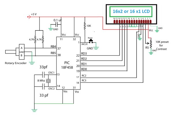
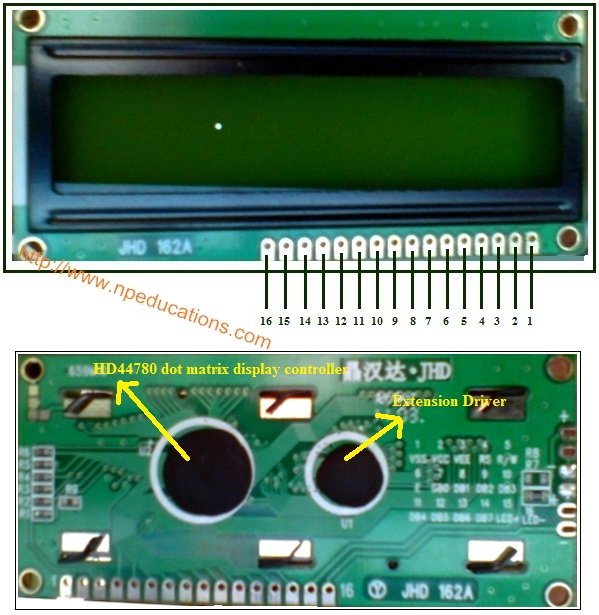
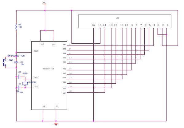
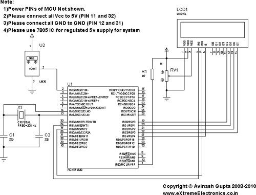
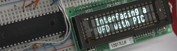
Parallel interfacing LCD with MCU at least need 6 I/O pins (4 bit mode) and maximun can up to 
11 I/O pins (8 bit mode). The I/O pin can be cut down to 3 pin by serial iterfacing using shift 
register. They were few shift register can be used such as 74HC164, 74HC595, CD4094 and any 
compatible 8 bit shift register. Before you attempt to do serial interfacing, it is good 
pratice to familiar with parallel interfacing. You can find many reference from internet. 
Following diagram show the serial interfacing Hitachi compatible 2 X 16 LCD modules with 
Pic16F84 or Pic16F628 MCU.

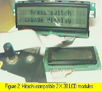
The Hitachi compatible 2 X 16 LCD modules drive by Pic16F84 MCU show on figure 1. The Hitachi compatible 2 X 20 LCD modules (optrex) drive by Pic16F84 MCU show on figure 2. When using this optrex 2 X 20 LCD modules, the Vref (pin 3 at LCD) need around -4.5v to -5.5V supply. The source code/hex file for Pic16f84 download here: F84SLCD.zip. The source code/hex file for Pic16f628 download here: 628SLCD.zip.

1. Serial interfacing LCD with Pic MicrocontrollerMore LCD reference can find here:

  1. www.myke.com
  2. www.eio.com
  3. www.repairfaq.org
  4. www.iaehv.nl
  5. www.shellyinc.com

2. Software SPI interfacing ADC with Pic16F84/Pic16F628

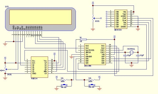
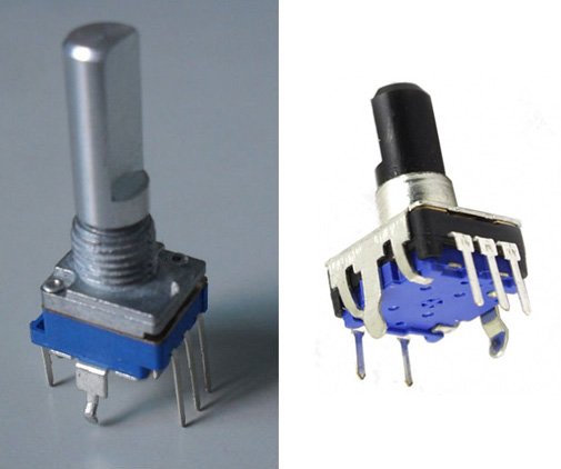
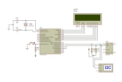
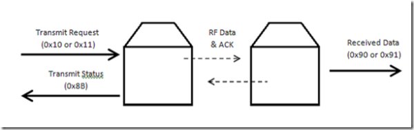
Communication with the MCP3028 ADC chip is done using a simple serial interface compatible
with the SPI protocol. The Pic16f84 or Pic16f628 didn't had hardware SPI peripheral. However, 
software implemeted SPI protocol can be done to communicate with 12 bit MCP3028 ADC device. 
The example of this communication shown as following circuit diagram. The ADC result shown
on LCD with hex value (conversion from binary code). Press the push button (pin 6, RB0/INT)
to select the ADC channel (8 channel from CH0 to CH7). Then, connect the potention meter to
the channel and turn it. You will see the hex value change accordingly. The SPI communication 
protocol need 4 line for interfacing. Using software implemeted SPI protocol enable 
communication with more than one ADC device. 
The hex file for Pic16f84 download here: F84S_L.zip.
The hex file for Pic16f628 download here: 628S_L.zip.

3. Simple multi channel digital voltmeter

The circuit diagram same as above 12 bit ADC interfacing. The only different is the source code
which the binary code has been change to ASCII code with decimen number. This need some math 
fuction such as divide function and floating point. The math fuction for assembler code can 
find from Microchip Website www.microchip.com. You can also find some documen of math fuction 
from www.piclist.com or use C compiler such as Piclite for PIC16f8X/c8x series, cc5x c, 
pacific c and so on. The following hex file are use Microchip Math Library (assembler code) for 
this simple multi channel digital voltmeter device (using 16 bit for calculation). The maximum 
hex value for the ADC channel is FFF equal to decimel number 4095. This will display on the LCD 
as 5.11 volt.

Download hex file for Pic16F84 here: F84dec.zip.
Download hex file for Pic16F628 here: 628dec.zip.
*Tip on source code migration from Pic16f8X series to Pic16f62X series*
  1. If using PORTA pins as interfacing I/O, you need to define/set the I/O fuction for PIC16f628. Generally, the initial PORTA setting as following for I/O fuction: clrf PORTA movlw 0x07 ;turn comparators off and movwf CMCON ;enable pins for I/O functions Note: Ensure the above setting done at Bank 0. The above setting especially important if you want to migrate the source code from Pic16f8X series to Pic16f62X series.
  2. Always refer to data memory MAP (on Pic datasheet) to ensure that the general purpose register used not out of range when migrate one type of MCU to another type of MCU. As example, general purpose register for Pic16f84 was 0x00c to 0x04f (at bank 0). For Pic16f628 was 0x020 to 0x07f (at bank 0), 0x0a0 to 0x0ef (at bank 1) and 0x120 to 0x14f (at bank 2). It is better to define the address follow sequence.If out of range, you can re-define it easly.
  3. When Using bit 4 (RB4) of PORT B of Pic16F62X series as a output pin, ensure that the MCU not programmed at low voltage program mode (see Microchip datsheet) if not it will set as Schmitt Trigger input and independence of TRISB regeister I/O direction setting.

Serial interfacing LCD with Pic Microcontroller SchematicStepper motor controller

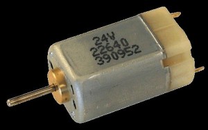
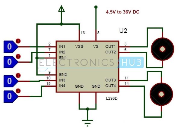
The stepper motor driver circuit shown as following
The opto-isolator are important which prevent destroy of MCU by the feeback voltage from 
power transistor. Two adjust-able voltage regulator used to adjust the running voltage and 
stopping/holding voltage of the stepper motor. The running voltage on by
the step pulse input which also signal to rotate the motor. The simple source
code using interrupt method to change the step sequence (one wave) download here:
F628_stepper for Pic16F628.
Simple mathematics algorithm able to drive more complicate step sequence (such as half step)
even for half_step 5phase stepper. 
Another stepper motor circuit for X-Y table project click here:X-Y table project

More stepper motor information refer to:

1)www.cs.uiowa.edu
2)www.ams2000.com

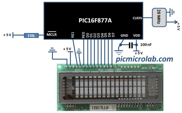
5). 24 segments LED display module

The numerical LED display module was widely used in display application. The most common numerical LED display module consists of either 8 segmented or 
16 segmented LED units. However, this type of display module only limited to display numerical character (0 to 9) and a few type of alphabet character. 
Most of alphabet word message displayed using alphanumerical LED modules with dot matrix arrangement.
The 24 segments LED display module designed in such a way that enable it to display  alphabet (A to Z) and numerical (0 to 9) character. 
This will able it to display most of word message using A to Z alphabet and numerical character when combine a few units of this module. 
The display controlling method also more simple than the dot matrix type of alphanumerical LED module.


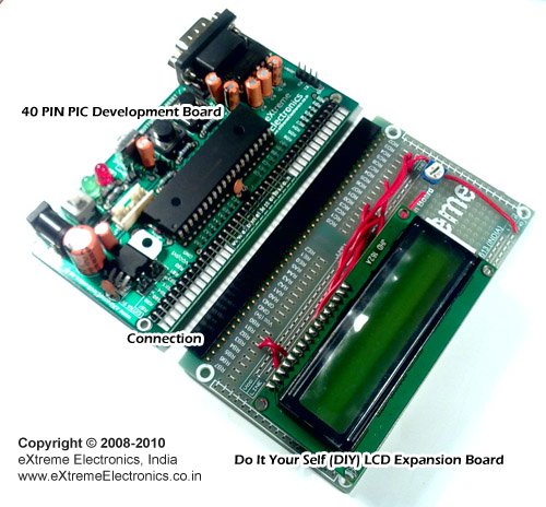
For more detail: 1. Serial interfacing LCD with Pic Microcontroller

Current Project / Post can also be found using:

  • pic microcontroller projects lcd
  • pic 16f84a lcd project circuit

The post 1. Serial interfacing LCD with Pic Microcontroller appeared first on PIC Microcontroller.


Rotary Encoder Interfacing with PIC Mirocontroller

$
0
0
i am currently working with some power supply design and i can say using conventional pots(potentiometer)  and rotary  switch  to adjust the voltage and other stuff is quite old school.
Rotary Encoder Interfacing with PIC Mirocontrollerso i have decided to go for a bit high tech , actually bit digital.
so here is the solution
Incremental Rotary Encoder
first of all i would like to tell you , these type of rotary encoder is totally digital component so you can’t directly replace these  with you conventional pots. so lets start what are Incremental Rotary Encoder ,
Rotary Encoder Interfacing with PIC Mirocontroller Schematic
Incremental rotary encoders by the looks of it just like a general purpose pot looks like but output is quite different they  provide a pair of digital signals that allow a microcontroller to determine the direction of a shaft’s rotation. They can be used to monitor motors and mechanisms, or to provide a control-knob user interface.

The post Rotary Encoder Interfacing with PIC Mirocontroller appeared first on PIC Microcontroller.

Interfacing DS1307 to PIC Microcontroller with C code and Circuit Diagram

$
0
0
This tutorial will help you to interface DS1307 RTC with PIC16F877 Microcontroller. The project is compiled in CCS Compiler and simulated with Proteus. The Real Time Clock is interfaced with PIC controller via I2C. I2C is a 2 wire communication protocol. I2C is used for moving data from one device to another simply and quickly. It is a serial, synchronous, Bi-Directional protocol, the data is synchronised  with clock through SCL pin and it controls when data is changed and when it should be read. All device is controlled by master device’s clock, No data is transferred in the absence of clock.
As mentioned above data is bi-directional, master device can both transmit and receive data. The serial data (SDA) and Serial Clock (SCL) pins must be pulled up with resistors, the value of resistors determine the speed of communication.
Interfacing DS1307 to PIC Microcontroller with C code and Circuit DiagramEmbedded C Program for DS-1307 I2C Communication
#include <16F877.h>
#include <lcd_4bit.c>
#use delay(clock=4000000)
#define RTC_SDA  PIN_C4
#define RTC_SCL  PIN_C3
#use i2c(master, sda=RTC_SDA, scl=RTC_SCL)
void rtc_get_time() ;
int convert(int k);
int sec,min,hr,k[20],z,k1[20];
int day1,date,month,year;
void main()
{SETUP_ADC(ADC_OFF);
lcd_init();
while(1)
{rtc_get_time();
lcd_cmd(0x80);
sprintf(k,”%02d:%02d:%02d”,hr,min,sec);
lcd_array(k);
lcd_cmd(0xc0);
sprintf(k1,”%02d:%02d:%02d “,date,month,year,);
lcd_array(k1);
lcd_cmd(0xc9);
switch(day1)
{
case 1: lcd_str(“Sunday”);
break;
case 2: lcd_str(“Monday”);
break;
case 3: lcd_str(“Tuesday”);
break;
case 4: lcd_str(“Wednesday”);
break;
case 5: lcd_str(“Thursday”);
break;
case 6: lcd_str(“Friday”);
break;
case 7: lcd_str(“Saturday”);
break;
} }}
void rtc_get_time()
{
  i2c_start();
  i2c_write(0xD0);
  i2c_write(0x00);
  i2c_start();
  i2c_write(0xD1);
  sec = i2c_read();
  min = i2c_read();
  hr  = i2c_read();
 day1=i2c_read();
 date=i2c_read();
 month=i2c_read();
 year=i2c_read(0);
  i2c_stop();
 Interfacing DS1307 to PIC Microcontroller with C code and Circuit Diagram
 sec= convert(sec);
 min= convert(min);
 hr= convert(hr);
 day1= convert(day1);
 date= convert(date);
 month= convert(month);
 year= convert(year);
 z=’a’;
if(hr>12)
{
hr=hr-12;
z=’p’;
}
}
int convert(int k)
{
int a0,a1,a;
 a0=((k&0x0F));
 a1=k>>4;
  a=((a1*10)+a0);
  return a;
}
Above shows  a simple program to read the Time value from DS-1307 IC. RTC Ds-1307 consumes very low power(500nA), so it can be backup by a battery for power failure issues.   For DS1307, the device address is D0. The data, for example seconds value, located in the zeroth register is taken and converted from BCD to integer, before displaying it on the LCD. We can also write the Time value to Ds1307 registers one by one.

The post Interfacing DS1307 to PIC Microcontroller with C code and Circuit Diagram appeared first on PIC Microcontroller.

Interfacing LCD with PIC Microcontroller – CCS C

$
0
0

In this tutorial we will see How to interface a 16×2 character LCD Module with PIC 16F877A Microcontroller using CCS C Compiler. 16×2 character LCD is a very commonly used LCD module in electronic projects and products. 16×2 means it can display 2 rows of 16 characters. It is a very basic and low cost module. Its other variants such as 16×1, 20×4 are available in the market. In these displays each character is displayed using 5×8 or 5×10 dot matrix. These LCDs commonly uses HD44780 compliant controllers for their operation.

Interface between a microcontroller and LCD can be 4-bit or 8-bit. The difference between 4-bit and 8-bit is how data are send to the LCD. To write an 8-bit character to the LCD module in 8-bit mode, ASCII data is send through the data lines DB0- DB7 and data strobe is given through the E line.

Interfacing LCD with PIC Microcontroller – CCS CBut 4-bit mode uses only 4 data lines. In this mode the 8-bit ASCII data is divided into 2 parts which are send sequentially through data lines DB4 – DB7 with its own data strobe through the E line. The idea of 4-bit communication is to save as much pins that used to interface with LCD. The 4-bit communication is a bit slower when compared to 8-bit. The speed difference is only minimal, as LCDs are slow speed devices the tiny speed difference between these two modes is not significant. Remember that our microcontrollers works in the speed of MHz range. Thus the 4-bit mode data transmission is most commonly used.

CCS C provides a built in library file, “lcd.c” for interfacing LCDs having HD44780 compliant controllers using 4-bit mode communication. Just include this file in your program and enjoy.

CCS C LCD Library

LCD Connections

For the proper functioning of LCD Library, you should define the connections of below 7 pins used for LCD interfacing in the program.

  • Enable – E or EN
  • Register Select – RS
  • Read / Write – RW
  • Data 4 – DB4 or D4
  • Data 5 – DB5 or D5
  • Data 6 – DB6 or D6
  • Data 7 – DB7 or D7

These must be defined before including the header file, it can be done in two ways as given below.

PORT Access Method

This method requires the entire 7 bit interface connected to same GPIO port. It should be defined before including the header file as shown below.

#define LCD_DATA_PORT getenv("SFR:PORTD")

This defines that the entire 7 bit interface is connected to PORTD of PIC Microcontroller.

PIN Access Method

In this method you can connect those 7 bits to any GPIO pins and it should be defined before including the header file as shown below.

//LCD Module Connections
#define LCD_RS_PIN PIN_D1
#define LCD_RW_PIN PIN_D2
#define LCD_ENABLE_PIN PIN_D3
#define LCD_DATA4 PIN_D4
#define LCD_DATA5 PIN_D5
#define LCD_DATA6 PIN_D6
#define LCD_DATA7 PIN_D7
//End LCD Module Connections

Important Functions

lcd_init()

This function must be called before any other lcd functions. It initializes the LCD module with above defined connections.
Interfacing LCD with PIC Microcontroller – CCS C Schematiclcd_putc(c)

This function will display c on the next cursor position of the LCD. You can print strings and characters using this function. You can also use following backslash character constants for sending different commands to LCD.

  • \\a – To set cursor to the upper left
  • \\f – To clear display and set cursor to upper left
  • \\n – To go to start of next line
  • \\b – To move back one position

lcd_gotoxy(x, y)

This function can be used to set cursor position of the LCD, upper left position is (1,1).

lcd_getc(x, y)

This function returns the character at the position (x, y) on the LCD.

lcd_cursor_on(int1 on)

This function can be used to turn the cursor on or off.
Example :

lcd_cursor_on(TRUE); //Turns ON the cursor
lcd_cursor_on(FALSE); //Turns OFF the cursor

Note : For more details you can read the library file “lcd.c” in the location C:/Program Files/PICC/Drivers/.


For more detail: Interfacing LCD with PIC Microcontroller – CCS C

Current Project / Post can also be found using:

  • lcd 16*2 projects with pic
  • serial communication using keypad and lcd display RS232 USING PIC
  • access control system using PIC18F4550
  • camera and lcd display circuit

The post Interfacing LCD with PIC Microcontroller – CCS C appeared first on PIC Microcontroller.

Interfacing xbee with PIC microcontroller using MikroC

$
0
0

In this tutorial, I will show how to interface an xbee module with PIC microcontroller.Here MikroC Pro for PIC compiler is used to write the code. Xbee modules communicates with host devices using serial communication.Most of the PIC microcontroller have UART module to support serial communication.

First of all we have to understand the two operating mode of xbee.

  • Transparent Mode
  • API Mode

Interfacing xbee with PIC microcontroller using MikroCInterfacing xbee in Transparent Mode

In transparent mode two xbee module makes just simple bridge of  serial communication.This is like just remove the wire of serial port and place two xbee module.In this mode if you send ‘A’ then another module will receive ‘A’.To send data write this code

void main() {
UART1_Init(9600);   // Initialize UART module at 9600 bps
Delay_ms(100);      // Wait for UART module to stabilize
UART1_Write(‘A’);
}
To receive this data on the other side write this code
char receive;
void main() {
UART1_Init(9600);  // Initialize UART module at 9600 bps
Delay_ms(100);   //Wait for UART module to stabilize
// If data is ready, read it:
if (UART1_Data_Ready() == 1)

{receive = UART1_Read();}}

Interfacing xbee in API Mode

API mode is main thing of a xbee module.You can make mesh networking,use of analog to digital pins(IO pins).In this mode all communications take place as structured data frame.Here some examples of data frame are shown:

AT Commands

The following image shows the API frame exchange that takes place at the UART when sending an AT command request to read or set a module parameter. The response can be disabled by setting the frame ID to 0 in the request.

Interfacing xbee with PIC microcontroller using MikroC schematicTransmitting and Receiving RF Data

The following image shows the API exchanges that take place at the UART when sending RF data to another device. The transmit status frame is always sent at the end of a data transmission unless the frame ID is set to 0 in the transmit request. If the packet cannot be delivered to the destination, the transmit status frame will indicate the cause of failure. The received data frame (0x90 or 0x91) is set by the AP command.you can get all the frames structures in datasheet.So we don’t proceed to explain each data frame.Our concern is to send these frames or receive these frames using PIC microcontroller.


For more detail: Interfacing xbee with PIC microcontroller using MikroC

The post Interfacing xbee with PIC microcontroller using MikroC appeared first on PIC Microcontroller.

Interfacing16X2 LCD with PIC Microcontroller

$
0
0

In this session we will see how to interface 16×2 LCD to PIC18F4550 microcontroller which is of family PIC18F. You can get information of 16×2 LCD in the session How to Interface 16X2 LCD with 8051 Microcontroller

Features of PIC18F4550:

  • PIC18F4550 belongs to the PIC18F family; PIC18F4550 is an 8bit microcontroller and uses RISC architecture. PIC18F4550 has 40 pins in PDIP (dual in line package) and 44 pin in TQFP (Quad flat package).
  • 32KB flash memory, 2048 bytes of SRAM (synchronous Random Access memory), EEPROM (Electrically Erasable Program Read Only Memory) of 256 bytes are embedded in the PIC18F4550.
  • It has 35 I/O pins for interfacing and communication with other peripherals, 13channel of 10bit analog to digital converters which are used for interfacing and communicating the analog peripherals (DC motor, LDR, etc.).

Interfacing16X2 LCD with PIC MicrocontrollerIt has 2 CCP and 1 ECCP module that is enhanced capture and compare module which is mainly used for modulation and waveform generation functions. CCP module is of 16bit register works as 16 capture bit register, 16 compare bit register, and PWM and duty cycle register.

  • PIC18F4550 has SPI (serial peripheral interface) and i2c (inter integrated circuit) for master and slave modes. It has SPP (Streaming Parallel Port) for USB streaming transfer.
  • PIC18F4550 is embedded with 4 timer modules (timer0 to timer3), 2 comparator modules and 3 external interrupt. It has Dual Oscillator options allow microcontroller and USB module to run at different clock speeds. It can operate in 2.0V to 5.5V

16X2 LCD Interfacing PIC Microcontroller – Circuit Explanation:

The resistor R1 is used for giving the contrast to the LCD. The crystal oscillator of 12 MHz is connected to the OSC1 and OSC2 pins of Pic microcontroller PIC18F4550 for system clock. The capacitor C2 and C3 will act filters to the crystal oscillator. You can use different ports or pins for interfacing the LCD before going to different ports please check the data sheet whether the pins for general purpose or they are special function pins.

Programming PIC for Interfacing 16X2 LCD:

Interfacing LCD to PIC is not different from interfacing to 8051. The basic concept and gist of the programming is almost same. Visit the following link for more information http://www.electronicshub.org/interfacing-16×2-lcd-8051/.

Only the pins, registers and architecture using for interfacing will be different. When we look at the program, functions like initialization, sending data to the LCD will be almost same.

In the pic programming also for initializing the LCD the R/W pin should be low for writing the data, Enable pins should be high and register select pin (RS) should be high for writing the data. For sending a command the RS should be low, R/W pin should be low and enable pin should be high.

Initializing the LCD function:

lcdcmd(0x38);//Configure the LCD in 8-bit mode,2 line and 5×7 font
lcdcmd(0x0C);// Display On and Cursor Off
lcdcmd(0x01);// Clear display screen
lcdcmd(0x06);// Increment cursor
lcdcmd(0x80);// Set cursor position to 1st line,1st column

Sending command to the LC:
  • rs=0;    Register select pin is low.                                                      
  • rw=0;  Read/write Pin is also for writing the command to the LCD.
  • en=1;enable pin is high.

Interfacing16X2 LCD with PIC Microcontroller schematicSending data to the LCD:

  • rs=1; Register select pin is high.
  • rw=0; Read/write Pin is also for writing the command to the LCD.
  • en=1; enable pin is high.
Steps for Programming:
  • Install MPLAB in your system and create a new project, in selecting device and family select PIC18F family and add PIC18F4550 controller to your project.
  • Select the compiler which you have installed and add the file to your project. After adding the file paste the code which is given below and run it. As it is a precompiled and tested program you will not find any errors.
  • After compiling the program with no errors dump the program into your development board using PICKIT2 or PICKIT3 programmer/ debugger.
  • If you are not using PICKIT then just compile the code and make the HEX file use this HEX file for programming the PIC microcontroller.


For more detail: Interfacing16X2 LCD with PIC Microcontroller

The post Interfacing16X2 LCD with PIC Microcontroller appeared first on PIC Microcontroller.

Interfacing LM35 Temperature Sensor with PIC Microcontroller.

$
0
0

The are many cool sensors available now a days, ranging from IR distance sensor modules, accelerometers, humidity sensors, temperature sensors and many many more(gas sensors, alcohol sensor, motion sensors, touch screens). Many of these are analog in nature. That means they give a voltage output that varies directly (and linearly) with the sensed quantity. For example in LM35 temperature sensor, the output voltage is 10mV per degree centigrade. That means if output is 300mV then the temperature is 30 degrees. In this tutorial we will learn how to interface LM35 temperature sensor with PIC18F4520 microcontroller and display its output on the LCD module.

Interfacing LM35 Temperature Sensor with PIC MicrocontrollerFirst I recommend you to go and read the following tutorial as they are the base of this small project.

After reading the ADC tutorial given above you will note the the PIC MCU’s ADC gives us the value between 0-1023 for input voltage of 0 to 5v provided it is configured exactly as in the above tutorial. So if the reading is 0 then input is 0v, if reading is 1023 then input is 5v. So in general form if the adc read out is val then voltage is.

unsigned int val;
val=ADCRead(0); //Read Channel 0
voltage= ((val)/1023.0)*5;

The above formula give voltage in Volts, to get Voltage in mili Volts (mV) we must multiply it with 1000, so

voltage=((val)/1023.0)*5*1000); //Voltage is in mV

since 10mV = 1 degree, to get temperature we must divide it by 10, so

t=((val)/1023.0)*5*100); //t is in degree centigrade

simplifying further we get

t=((val/1023.0)*500);
t=(val*0.48876);

we round off this value, so

t=round(val*0.48876);

remember round() is a standard c library function

Interfacing LM35 Temperature Sensor with PIC Microcontroller schematicHardware for LM35 based thermometer.

You will need a PIC18F4520 chip running at 20MHz attached with a standard 16×2 LCD Module and LM35 on AN0 pin. LM35 is a 3 pin device as show below.

connect the +Vs Pin to 5v and GND to GND. The output must be connected to the analog input pin 0 of the PIC18F4520 MCU. It is labeled AN0 in the datasheet. It is pin number 2 on the 40 pin package. It is also called RA0 because it is shared with PORTA0.

We will use our 40 PIN PIC Development board to realize the project. The base board has all the basic circuit to run the PIC. The extra part required for this project like LCD and the LM35 temperature sensor are installed in the expansion board.


For more detail: Interfacing LM35 Temperature Sensor with PIC Microcontroller.

Current Project / Post can also be found using:

  • Circuit for fire fighting robot using pic mcro 16f887a
  • pic programming for robot

The post Interfacing LM35 Temperature Sensor with PIC Microcontroller. appeared first on PIC Microcontroller.

Interfacing Temperature Sensor with Microchip PIC16F876A

$
0
0

The tutorial aims at providing the necessary information for interfacing an analog type temperature sensor with a Microchip PIC Microcontroller. PIC (Peripheral Interface Controllers) was introduced in 1985. The PIC16F876A has 8K of Flash Program Memory, 368 bytes of Data Memory (RAM) and many other attractive features. Some features are ADC, USART, and 14 Interrupts all in 28 PDIP Package.

mperature Sensor with Microchip PIC16F876AThe Analog temperature sensor used is LM35. It has a transfer function of 10mv/’c. The output of LM35 is analog voltage which varies with changes in temperature. This analog voltage is digitized using the On-Chip 10bit A/D Converter and the value is displayed on a 2×16 LCD.

It is possible to switch On/Off an external application based on temperature value.

The LCD is based on HD44780 controller. The programming has been done using the MikroC compiler from Mikroelektronika (www.mikroe.com). The demo version has a 2KB Hex Output limit, fortunately it is more than enough for our requirement.

Program

int t1,temp;

char *text[6];

void main()

{adcon1=14;

lcd_init(&portb);

lcd_out(1,1,”Temperature”);

lcd_out(2,8,”‘C”);

while(1)

{t1=adc_read(0);

//temp=0.245*t1;          // For TMP37 Sensor 20mv/’c

temp=0.245*t1*2;        // For Lm35 Sensor 10mv/’c

inttostr(temp,text);

lcd_cmd(lcd_cursor_off);

lcd_out(2,1,text);

delay_ms(100);}}

Interfacing Temperature Sensor with Microchip PIC16F876A SchematicThe program is self explanatory, however let me explain you the calculation done. In a while loop. The Input channel 0 is read and the digitized value is obtained. Now the smallest digitized value is equal to Vref/((2^10)-1). Internal Vref is 4096mV but we will consider 5000mV for the ease of calculation. Multiplying the value obtained above with the digitized value will give us the analog voltage. Since the transfer function of Lm35 is 10mV/’c, we can obtain the temperature.


For more detail: Interfacing Temperature Sensor with Microchip PIC16F876A

The post Interfacing Temperature Sensor with Microchip PIC16F876A appeared first on PIC Microcontroller.


Interfacing DC Motor with PIC Microcontroller using L293D

$
0
0

DC Motor and L293D

We can’t drive a DC Motor (depends) directly with a Microcontroller, as DC Motors requires high current and high voltage than a Microcontroller can handle. Microcontrollers usually operates at +5 or +3.3V supply and it I/O pin can provide only up to 25mA current. Commonly used DC Motors requires 12V supply and 300mA current, moreover interfacing DC Motors directly with Microcontrollers may affect the working of Microcontroller due to the Back EMF of the DC Motor. Thus it is clear that, it not a good idea to interface DC Motor directly with Microcontrollers.Interfacing DC Motor with PIC Microcontroller using L293D

The solution to above problems is to use H-bridge circuit.

It is a special circuit, by using the 4 switches we can control the direction of DC Motor. Depending upon our power requirements we can make our own H-bridge using Transistors/MOSFETs as switches. It is better to use ready made ICs, instead of making our own H-bridge.

L293D and L293 are two such ICs. These are dual H-bridge motor drivers, ie by using one IC we can control two DC Motors in both clock wise and counter clockwise directions. The L293D can provide bidirectional drive currents of up to 600-mA at voltages from 4.5 V to 36 V while L293 can provide up to 1A at same voltages. Both ICs are designed to drive inductive loads such as dc motors, bipolar stepping motors, relays and solenoids as well as other high-current or high-voltage loads in positive-supply applications. Interfacing DC Motor with PIC Microcontroller using L293D schematicAll inputs of these ICs are TTL compatible and output clamp diodes for inductive transient suppression are also provided internally. These diodes protect our circuit from the Back EMF of DC Motor.

In both ICs, drivers are enabled in pairs, with drivers 1 and 2 are enabled by a high input to 1,2EN and drivers 3 and 4 are enabled by a high input to 3,4EN. When drivers are enabled, their outputs will be active and in phase with their inputs. When drivers are disabled, their outputs will be off and will be in the high-impedance state.


For more detail: Interfacing DC Motor with PIC Microcontroller using L293D

Current Project / Post can also be found using:

  • Motar pule pic
  • motorized movement projects
  • pic microcontroller for motor pdf

The post Interfacing DC Motor with PIC Microcontroller using L293D appeared first on PIC Microcontroller.

IR-Sensor Circuit and Interfacing with PIC Microcontroller

$
0
0

An IR sensor is an electronic device, that produces in order to detect some parts of the environs. An infrared sensor can measure the heat of an object as well as detects the motion. These sensors are used to measure only IR radiation, rather than producing it that is called as a passive infrared sensor. Generally in the IR spectrum, all the surrounding objects generate different form of thermal radiation.These kinds of radiations are not observable to our eyes, that can be sensed by an IR sensor. The emitter of the sensor is infrared LED and the sensor is an IR photodiode which is sensitive to infrared light of the same wavelength as that produced by the infrared LED.IR Sensor Circuit and Interfacing with PIC Microcontroller When infrared light drops on the photodiode, the resistances and o/p voltages change in proportion to the received magnitude of the infrared light.

What is Infrared Sensor?

IR sensor is an electronic device which is used to sense heat & objects. It works with the sensing of IR radiations and variation in heat in its nearby. IR sensors are classified into two types such as photo IR sensor and thermal IR sensor.

  • A thermal infrared sensor detects the change of heat from its nearby objects
  • The photo IR sensor uses a photo diode to sense IR radiations. In this article as an infrared sensor a photo IR sensor is used to build the circuit.

The applications of the infrared sensors involve from domestic devices to industrial devices. These sensors are used in object sensing, motion detectors, obstacle avoidance robot, gas leakage detection, smoke detection, measurement of distance, robotics and many more.

Infrared Sensor Circuit with Working

The IR sensor circuit diagram is shown below. In the circuit below, the main parts of this sensor are photo diode and the IR receiver LED. Photo diode emits IR radiations when it strikes to any object, then turn back with some angle. The IR receiver detects reflected radiations. Because in this circuit, we are using a photo diode, so this type of sensor is called a photo infrared sensor.

The Required Components of Photo Infrared Sensor include IR receiver TSFF5210, Photodiode, 100 ohm resistor, 10k resistor, 10k variable resistor and LM358 IC. IC Lm358 is used as a comparator when IR receiver senses IR radiations. When the o/p of lm358 goes high, then LED connected at the o/p turns ON. The output pin of the IC LM358 is used to interface with PIC microcontroller.IR Sensor Circuit and Interfacing with PIC Microcontroller schematic

IR Sensor Circuit Interfacing with PIC18F4550 Microcontroller

The output of the infrared sensor circuit is connected to PIC microcontroller pins and the microcontroller will take it as digital input either 0 or 1. According to the o/p of the infrared sensor module, the microcontroller will react by glowing LED.

The o/p of the infrared sensor circuit is connected to RA0 pin of the pic microcontroller. It is arranged as i/p with TRISB registers and the o/p of this interfacing will be displayed on LED that is connected across PORTD includes RD5, D6, RD7. Here o/p pins are RB0 and RB1.

For more detail: IR-Sensor Circuit and Interfacing with PIC Microcontroller

The post IR-Sensor Circuit and Interfacing with PIC Microcontroller appeared first on PIC Microcontroller.

Interfacing DC Motor with 8051 Microcontroller

$
0
0

When we talk about controlling the robot, the first thing comes into the mind is controlling DC motors. Interfacing DC motor to the microcontroller is very important concept in Robotic applications. By interfacing DC motor to the microcontroller, we can do many things like controlling the direction of the motor, controlling the speed of the motor. This article describes you how to control the DC motor using AT89C51 controller.

Interfacing DC Motor to 8051 Circuit Principle:

The maximum output current of microcontroller pin is 15mA at 5V. But the power requirements of most of DC motors is out of reach of the microcontroller and even the back emf (electro motive force) which is produced by the motor may damage the microcontroller. Hence it is not good to interface DC motor directly to the controller. So use motor driver circuit in between of DC motor and controller.Interfacing DC Motor with 8051 Microcontroller

Also read the interesting concept: Interfacing 7 Segment Display to 8051 Microcontroller

Here, we are using L293D motor driver IC to drive DC motors. Using this IC, we can drive 2 DC motors at a time. For this IC motor supply is variable 4.5 to 36V and it provides maximum current of 600mA.

Circuit Diagram of Interfacing DC motor to 8051 Microcontroller:

Circuit Components:

  • at89c51 microcontroller
  • PCB board
  • programming cable
  • 12V DC battery or Adaptor
  • L293D motor driver
  • DC motor
  • Electrolytic capacitor – 10uF
  • 2 Ceramic capacitors – 33pF
  • 10k resistors (1/4 watt) – 3
  • push buttons – 2
  • Connecting sires.

Get an idea about How PWM Based DC Motor Speed Controlling Circuit Works using Microcontroller

Interfacing DC Motor to 8051 Circuit Design:

The major components in the above circuit diagram are at89c51 microcontroller and motor driver. Here the motor driver input pins IN1, IN2 are connected to the P3.0 and P3.1 respectively to control the motor directions. DC motor is connected to output terminals of L293D. EN1 pin is connected to the 5V DC to drive the motor. Switches are connected to the P2.0 and P2.1 in pull down configuration. First switch rotates the motor in clockwise direction and second switch rotates the motor in anti clockwise direction. 8th pin of motor driver is connected to the battery directly.Interfacing DC Motor with 8051 Microcontroller schematic

 L293D Motor Driver:

L293D is a quadruple H- bridge motor driver, as the name suggests it used to drive the DC motors. This IC works based on the concept of H- Bridge. H-bridge is a circuit which allows the voltage in either direction to control the motor direction.

There are 4 input pins for L293D. Motors directions depends on the logic inputs applied at this pins. EN1 and EN2 must be high to drive the 2 DC motors.

  • IN1=0 and IN2=0 ->  Motor1 idle
  • IN1=0 and IN2=1 -> Motor1 Anti-clock wise direction
  • IN1=1 and IN2=0 -> Motor1 Clock wise direction
  • IN1=1 and IN2=1 -> Motor1 idle
  • IN3=0 and IN4=0 -> Motor2 idle
  • IN3=0 and IN4=1 -> Motor2 Anti-clock wise direction
  • IN3=1 and IN4=0 -> Motor2 Clock wise direction
  • IN3=1 and IN4=1 -> Motor2 idle

For more detail: Interfacing DC Motor with 8051 Microcontroller

Current Project / Post can also be found using:

  • Projects of motor
  • dc motor speed and direction control using pic16f877a and h-bridge pdf
  • how to control motor in pic circut diagram
  • how to make a home motor with pic

The post Interfacing DC Motor with 8051 Microcontroller appeared first on PIC Microcontroller.

Know the Procedure of GSM Modem Interfacing with 8051

$
0
0

The acronym of the GSM modem is Global System for Mobile Communications, it is a wireless communication module, used to  make a computer or any processor to communicate over a network. This modem uses a variation of TDMA(Time Division Multiple Access) and is the most commonly used of the digital wireless telephony technologies like TDMA, GSM and CDMA.A GSM modem needs a SIM card to operate through a n/w range subscribed by the network operator. This modem can be connected to a computer via a serial, Bluetooth or USB connection. A GSM modem is also a standard GSM mobile phone with a suitable cable and software driver to connect to a USB port on your PC. Generally, this modem is preferred instead of a GSM mobile phone. This article describes how GSM modem interfacing with 8051 microcontroller.Know the Procedure of GSM Modem Interfacing with 8051

GSM Modem Interfacing with 8051 Microcontroller

Nowadays, many projects like  car security system, home automation, remote controlled industrial machines are controlled by an SMS using GSM modem. This modem uses a SIM card and operates through a subscription with the mobile operator. Many people they don’t know how GSM module interfacing with 8051 microcontroller. Therefore, the following steps explain the basics of how GSM modem interfacing with 8051 microcontroller.

Steps to Interfacing a GSM Modem to the Microcontroller

Step1: Arranging the GSM Modem

The GSM modem is a one type of modem, which uses the SIM card for communication. First, insert a SIM card into the modem which uses the same number/ account as the caller phone. It supports AT commands for handling the messages. These commands are programmed into the microcontroller ensures ending or receiving of the SMS from the modem.
For instance: Initializing commands for several types of modem are shown below

  • Siemens: AT+CNMI=1,1,0,2,1
  • WaveCom: AT+CNMI=2,1,0,1,1
  • SonyEricsson: AT+CNMI=3,1,0,1,0
  • Motorola USB modem: AT+CNMI=3, 1,0,0,0
  • The modem is arranged to send notifications to the microcontroller upon receiving a new text.
  • Arrange the modem port speed as a rule such as 9600 or 19200 bps baud rates.

Step2: GSM Modem Testing

The GSM modem comprises of two light emitting diodes like green and red LEDs, which are used for the network connection indication. If there is no network is available, then the red LED glows, and if a network is available, then the green LED glows so that one can observe the working of GSM modem. Connect a power supply to a GSM modem which contains a SIM card and wait till it registers in the GSM network. For the testing of the modem, you can send an SMS to the modem. If it receives the message from the mobile, it is working properly, or else it is damaged.

Step3: GSM Modem Interfacing with 8051 Microcontroller

GSM modem works with 12V DC and the microcontroller works with 5V. So, interfacing of this modem with microcontroller directly is not possible due to mismatch of voltage levels. GSM modem is interfaced with 8051 microcontroller through MAX232 with the help of RS232 cable for serial communication. MAX232 device is used to convert TTL logic level to RS232 level during serial communication of microcontroller to the GSM modem. The RS232 device is an interface between data terminal equipment and data communication equipment using serial binary data exchange. The RS232 cable is commonly available with the 9 or 25 pin wiring and has jumpers to provide handshaking pins for those devices that require it.Know the Procedure of GSM Modem Interfacing with 8051 schematic

Step4: Microcontroller Programming

  • Transmitting single character
  • Transmitting word
  • Receiving char

#include<reg51.h>
voidinit_RS 232();
voidTx_Char(unsigned char ch);
voidTx_String(unsigned char *str);
voidRx_Char();
voidinit_RS 232()
{
TMOD|=0×20;    //Timer 1 in mode 2 ( Auto Reload mode)
TH1=0XFD;        //0xFD for 9600bps
SCON=0×50;        //Enable TI and RI pins using Serial control Register
TR1=1;        //Start Timer 1;
}
voidTx_Char(unsigned char ch)
{
SBUF=ch;        // Load the character into SBUF register to transmit.
while(!TI);        //wait for TI flag to raise high

TI=0;            //clear TI for further transmission.
}
voidTx_String(unsigned char *str)
{
while(*str)
Tx_Char(str++);
}
voidRx_Char()
{
while(RI==1);    //wait for RI flag to receive any character
Ch=SBUF;        // capture the character from SBUF into Ch variable
RI=0;            //clear RI flag for further reception
}
In addition to the above program,if an operator wants to make an SMS to any other persons mobile via  microcontroller upon interrupt either from internal or external device, the operator can follow the below program.

For more detail: Know the Procedure of GSM Modem Interfacing with 8051

The post Know the Procedure of GSM Modem Interfacing with 8051 appeared first on PIC Microcontroller.

DS18S20 interfacing with pic and avr microcontroller

$
0
0

In this article you will learn how to interface temperature sensor DS18S20 with PIC16F877A microcontroller and atmega88 avr microcontroller. Complete interfacing circuit diagram and code for both PIC microcntroller and AVR microcontroller. DS18S20 interfacing with pic code is written using Mikro C for pic. Code for AVR microcontroller is written using Mikro basic complier for avr. Let’s start with basic introduction of DS18S20 digital thermometer.DS18S20 interfacing with pic and avr microcontroller

DS18S20 digital thermometer

DS18S20 is  9- bit digital thermometer which is used to measure celsius tempertaure. DS18S20 also have fuction of alaram with non-volatile user programmed points. It communicates with microcontrollers with only one wire. So it works with one wire communication protocol. It requires only one data line for communication. It can also be powered from data line. It remove the need of external power supply. Each DS18S20 have unique 32 bit address. Therefore it is  easy to interface multiple DS18S20’s with microcontroller.

DS18S20 applications

It have many applications. Some major applications are given below.

  • industrial temperature controller
  • buildings temperature controller
  • digital thermometers

DS18S20  features

It have following major features as compared to other digital thermometers:

  • one wire interfacing with microcontroller i.e. only one wire is required for data
  • alarm setting if temperature is outside permissible limits
  • Multiple devices can be interfaced with same microcotroller due to unique 64 bit address
  • Maximum accuracy
  • It can read temperature from -55°C to +125°C
  • No need of external components. It is ready to use by interfacing with microcontroller

DS18S20 pin configuration

It is available in 3 pin TO-92 package and 8 pin SO package

We are using 3 pin ds18s20 package in this tutorial.  Brief description of all the pins is given below:

  1. Number 1 : ground pin
  2. number 2: Data input and output pin. It is open drain one wire interfaced pin. It is also used for powered DS18S20.
  3. number 3:  5 volt power supply if not used in parasite power mode. if parasite power mode is used, it must be groundedDS18S20 interfacing with pic and avr microcontroller schematich

DS18s20 interfacing with PIC16F877A microcontroller

Circuit diagram for interfacing of DS18S20 is shown below. It is not used in parasite power mode. Therefore 5 volt power is connected externally.  DS18S20 is interfaced with pin zero of port D. PORT D pin zero is used for one wire communication with digital thermometer.  16 ×2 LCD is used to display temperature. LCD interfacing with pic microcontroller is used to display temperature.

DS18S20 interfacing with pic code

Code for this project is written using Mikro C pro for pic.


For more detail: DS18S20 interfacing with pic and avr microcontroller

The post DS18S20 interfacing with pic and avr microcontroller appeared first on PIC Microcontroller.

Real Time Clock (RTC) Interfacing PIC18F

$
0
0

Introduction to RTC:

Real time clock also referred as RTC is an important device or integrated circuit which will keep the track of current time. RTC is mainly used in computers, mainframes servers and embedded applications (mobile phone, tablets, organizers, PDA etc).

The main function of the RTC is to keep the track of time of the device even though it is in off or turned off state. The best example is your computer, even though if you shut down your computer for really long time you can see the exact time on your desktop.

Battery is used as external power source and connected to the RTC, to keep the track of the system time even if your computer or embedded system is turned off.  If we use lithium battery as external power source RTC will work minimum 3 years even if your system is turned off.Real Time Clock (RTC) Interfacing PIC18F

Pin Configuration of PCF8563:

PCF8563 is a RTC and Calendar developed by NXP Semiconductor.PCF8563 uses bidirectional I2C (inter integrated circuit) for interfacing with other peripheral. The bus speed is 400 kbps and incremented automatically after each written or read data byte.

There are 8 pins which are on the IC as seen in the below figure

  • OSC1 and OSC0: These two pins connected by the 32.768 kHz crystal oscillator and which provide the source clock for the circuit.
  • INT: This pin mainly used to provide an external interrupt to the RTC. For example: in alarm application after the alarm occur it should set back to original state, to set back it to original state the user must give an interrupt to the RTC.
  • Vss: Ground
  • Vdd: Vdd is the pin where we have to give the supply voltage to the RTC. Battery is connected to the Vdd for uninterrupted power supply, even if the main supply voltage is turned off. The operating voltages are 1V- 5V.
  • CLKOUT: for all the application we cannot use 32.768 kHz clock for other application we may need small clock like 32 Hz, 1 Hz for microcontroller clock , input to the charge pump etc.
  • SCL and SDA: SCL is serial clock; SDA serial data pins which are mainly used to interface with the other peripherals through I2c (inter integrated circuit). Through these pins only data is exchanged between the other peripherals and RTC. Clock is given to the SCL and Data is given to the SDA.

Functional Features of PCF8563:

  • Provides year, month, day, weekday, hours, minutes, and seconds based on a 32.768 kHz quartz crystal.
  • Battery backup input pin and switch-over circuit.
  • Freely programmable timer and alarm with interrupt capability.
  •  Selectable integrated oscillator load capacitors for CL = 7 pF or CL = 12.5 pF.
  •  Internal Power-On Reset (POR).
  •  Open-drain interrupt or clock output pins.
  •  Programmable offset register for frequency adjustment.

PIC Microcontroller:

Peripheral Interface controller is developed by general instruments in the year 1975. Hardware architecture and reduced instruction set are used in it. Peripherals like ADC, PWM, OP-AMPS, TIMERS, CAPTURE/COMPARE and DAC etc are inbuilt in PIC microcontroller. Communication protocols like I2C, SPI (serial peripheral Interface) USART (Universal Synchronous Asynchronous Receiver Transmitter), CAN (Control Area Network), ETHERNET are used to communicate with the other external peripheral which are connecter to the PIC micro controller.

PIC is available in different architectural like 8 bit, 16 bit, 32 bit. According to the application we can use the architecture.

PIC 18F45K80 is a PIC 16 bit microcontroller developed by microchip and it belong to PIC 18F66K80 family. PIC 18F45k80 has 40 pin in PDIP (Plastic Dual Inline Package) and 44 pin in TQFP (Thin Quad Flat Package).

PIC 18F45K80 Features:

  • Program memory of 32 Kbytes and data memory of 3648 bytes
  • 40-44 pins and 35 I/O pins
  • Operating Voltage Range: 1.8V to 5.5V
  • On-Chip 3.3V Regulator
  • Operating Speed up to 64 MHz
  •  Up to 64 Kbytes On-Chip Flash Program Memory
  • Five CCP/ECCP modules
  • Five 8/16-Bit Timer/Counter modules  and Two Analog Comparators
  • Configurable Reference Clock Output
  • Charge Time Measurement Unit (CTMU) and  One Master Synchronous Serial Port (I2c and SPI)
  • Two Enhanced Addressable USART modules 12-Bit A/D Converter with up to 11 Channels Data Signal Modulator module.

PIN Diagram of PIC Microcontroller:

Related Post: PIC Microcontroller Architecture

Interfacing PIC with RTC:

Connect the RTC SDL and SCL pins to the PIC controller pins through the pull up resistor (Pull up resistor is nothing but giving the voltage to the resistors (5k – 10k) to the SDL and SCL wires, here we should give VCC voltage which is 5v).  Using the serial interface we can see the output in the terminal.Real Time Clock (RTC) Interfacing PIC18F schematiche

Circuit Diagram:

So by seeing the circuit we can easily understand how the connections are given. But care should be taken with the resistance value. The total project can be divided into three steps

  • Interfacing PIC18F to RTC.
  • Interfacing UART to PIC18F for serial communication purpose to see the RTC output in HyperTerminal of PC.
  • Interfacing RTC output to the Serial communication.

NOTE: same circuit and code can be used for PIC 16F and PIC18F series. In the code you have to change the pin configurations only in the initialization functions.


For more detail: Real Time Clock (RTC) Interfacing PIC18F

The post Real Time Clock (RTC) Interfacing PIC18F appeared first on PIC Microcontroller.

PIC32MX: Interfacing to a Secure Digital (SD) Flash Card

$
0
0

Original Assignment

Do not erase this section!

Your assignment is to create code that will allow the PIC32 to read and write data to a FAT32 SD card. The SD card should be able to be read by a PC after data has been written on it by the PIC32.

Create functions so that it is easy to read, write and initialize the SD card.

Use the example projects in the “Microchip Solutions/USB Device – Mass Storage – SD card data logger” and “Microchip Solutions/USB Device – Mass Storage – SD card reader” folders as a guide.

Use your code to create a folder on the PIC32 and write 1000 bytes of data to a text file in that folder. How long does it take? Make sure the PC can read the file.

Interfacing to a Secure Digital (SD) Flash Card

Create a folder on the SD card with the PC and place a text file in the folder with 1000 bytes of data. Read the file with the PIC32. How long does it take?

Overview

Secure digital cards, or SD cards, are inexpensive and common mass storage devices that can be interfaced with our PIC to provide a larger non-volatile data storage space. Non-volatile memory is computer memory that retains information even when not powered. In this lab, we interfaced our PIC32MX460F512L to communicate with a 2GB FAT32 SD card to allow reading and writing of data.

The original program stems from tutorials from the book Programming 32-bit Microcontrollers in C: Exploring the PIC32 by Lucio Di Jasio. We used the tutorials from Day 14 and 15 to generate our code for SD card reading and writing via SPI communication (Serial Peripheral Interface). The main problem with this tutorial is that it is made for the PIC32MX360F512L on the Explorer16 board, so many changes were required in order to run the code.

NOTE: While ultimately, we were able to initialize the SD card and send data along the output and input lines, we were unsuccessful in executing the read/write demo. We are confident that the hardware configuration and circuit are correct, however the code likely contains errors.

Circuit

The SD card holder has 11 pins, 6 of which are being directly used for communication with our PIC. The SD card is powered off of 3.3V from our PIC, which comes from our mini-usb connection. 10K and 1K resistors pull-up resistors were added to each connection in order to allow for a voltage drop. Green and yellow LEDs were added to the Write Protect (WP) and Card Detect (CD) lines for ease of use. A powered yellow LED indicates the presence of an SD card in the SD card reader. A powered green LED indicates that the Write Protect is off. No resistor is necessary on the clock line. The IRQ and P9 pins on the SD card holder were not needed for SPI communication, so they were not connected to the PIC. However, they need to be powered for the SD card holder to operate properly. A breakdown of each of the 11 pins on the SD card holder is displayed in the table below.

NOTE: While ultimately, we were able to initialize the SD card and send data along the output and input lines, we were unsuccessful in executing the read/write demo. We are confident that the hardware configuration and circuit are correct, however the code likely contains errors.

Interfacing to a Secure Digital (SD) Flash Card

Circuit

The SD card holder has 11 pins, 6 of which are being directly used for communication with our PIC. The SD card is powered off of 3.3V from our PIC, which comes from our mini-usb connection. 10K and 1K resistors pull-up resistors were added to each connection in order to allow for a voltage drop. Green and yellow LEDs were added to the Write Protect (WP) and Card Detect (CD) lines for ease of use. A powered yellow LED indicates the presence of an SD card in the SD card reader. A powered green LED indicates that the Write Protect is off. No resistor is necessary on the clock line. The IRQ and P9 pins on the SD card holder were not needed for SPI communication, so they were not connected to the PIC. However, they need to be powered for the SD card holder to operate properly. A breakdown of each of the 11 pins on the SD card holder is displayed in the table below.

NOTE: While ultimately, we were able to initialize the SD card and send data along the output and input lines, we were unsuccessful in executing the read/write demo. We are confident that the hardware configuration and circuit are correct, however the code likely contains errors.


For more detail: PIC32MX: Interfacing to a Secure Digital (SD) Flash Card

The post PIC32MX: Interfacing to a Secure Digital (SD) Flash Card appeared first on PIC Microcontroller.


Interfacing VFD with PIC Microcontroller

$
0
0

Vacuum fluorescent display can be a good alternative to a Liquid-crystal displays in some applications. They have a number of advantages over LCD like extended temperature range and excellent contrast in high brightness environment.Interfacing VFD with PIC Microcontroller The main disadvantage is higher power consumption making them less attractive in battery operated devices. In this post I’ll show you how you can use this type of display with microcontroller. You can purchase them on Ebay as I did here.CU16025 VFD module was used for this purpose as a direct replacement for 2×16 LCD display. Although the manufacturer of these modules provides some code examples I’ve used my own driver code (originally written for a LCD) and a parallel 8 bit connection to interface this display with PIC16F877A microcontroller. I’ve adapted assembly language subroutine that I wrote earlier for VFD module initialization and for sending data/command. The code was written in C in MPLAB X using XC8 compiler. The same subroutine was also used in VFD Voltmeter project. As you can see from the schematic below 2 PORTs were used to control the display. PORTD for data/command and PORTE for RS and Enable lines.Interfacing VFD with PIC Microcontroller schematich

The code consist of 3 main functions: Display initialization, WriteDataVFD , WriteCommandVFD. Command for example can be an address of one of the segments and data is the character you want to display in ASCII. Comments in the source code should provide you  with more detailed explanation on each instruction. Click here to download the code.


For more detail: Interfacing VFD with PIC Microcontroller

The post Interfacing VFD with PIC Microcontroller appeared first on PIC Microcontroller.

Interfacing VFD with PIC Microcontroller

$
0
0

Vacuum fluorescent display can be a good alternative to a Liquid-crystal displays in some applications. They have a number of advantages over LCD like extended temperature range and excellent contrast in high brightness environment. The main disadvantage is higher power consumption making them less attractive in battery operated devices.Interfacing VFD with PIC Microcontroller In this post I’ll show you how you can use this type of display with microcontroller. You can purchase them on Ebay as I did here.CU16025 VFD module was used for this purpose as a direct replacement for 2×16 LCD display. Although the manufacturer of these modules provides some code examples I’ve used my own driver code (originally written for a LCD) and a parallel 8 bit connection to interface this display with PIC16F877A microcontroller. I’ve adapted assembly language subroutine that I wrote earlier for VFD module initialization and for sending data/command. The code was written in C in MPLAB X using XC8 compiler. The same subroutine was also used in VFD Voltmeter project. As you can see from the schematic below 2 PORTs were used to control the display. PORTD for data/command and PORTE for RS and Enable lines.Interfacing VFD with PIC Microcontroller schematich

The code consist of 3 main functions: Display initialization, WriteDataVFD , WriteCommandVFD. Command for example can be an address of one of the segments and data is the character you want to display in ASCII. Comments in the source code should provide you  with more detailed explanation on each instruction. Click here to download the code.


For more detail: Interfacing VFD with PIC Microcontroller

The post Interfacing VFD with PIC Microcontroller appeared first on PIC Microcontroller.

10 tricks for interfacing to the PIC16C508

$
0
0

Most of the ideas in this chapter can be found on the pages of this website, but just in case you want to go over the capabilities of the ‘508A, we have brought them together.

Quite often when you are programming, the first thing you will run out of is output lines. Many projects need lots of drive lines and if you need more than about 8, you should go to another micro-controller.

Don’t expect an 8-pin chip to perform the impossible.

The designers of the ‘508A have done an amazing job providing 5 output lines (and one input line) in an 8-pin chip, but even so, many projects run out of drive-lines.

On other pages of this course we have shown how to expand the drive lines with a binary counter or shift register. This can increase the lines to more than 10 however if you want to add just one or two more devices than the chip is directly capable of handling (5), there are clever ways to connect them to the chip.10 tricks for interfacing to the PIC16C508

1. LED AND PIEZO ON ONE LINE

One of the simplest combinations is a LED and Piezo on a single drive-line as shown in fig: 1. These can be combined because the requirements of a LED are different to a piezo. A LED requires a constant HIGH for it to illuminate while a piezo requires a HIGH-LOW-HIGH waveform at approx 3kHz to produce a tone.

If the mark-space ratio of this waveform is kept short as shown in fig: 2, the LED will only illuminate very dimly. A short mark-space ratio means the “mark” is very small compared to the “space”. A very short on-time (mark) and a long off-time (space) will not affect the tone from the piezo but will deliver very little energy to the LED and this is exactly what we want.

On the other hand, each time the LED is activated, only a very small click will be heard, and this will hardly be noticeable. In this way the two devices can be combined on the same line.

2. LED AND PUSH BUTTON ON ONE LINE

In this book, we show how to connect two and up to five or more push buttons on a single input line and generally you will not have any problems adding buttons to a project. But if you want to add a secret reset button (or a “cheat” button, for example), it can be added across an existing LED as shown in fig: 3.

The resistor between the switch and micro acts as a safety resistor to prevent the output of the chip being damaged if the switch is pressed when the LED is activated, and it also acts as a dropper resistor for the LED.

These two items will work in combination because the impedance of the LED is very high when no voltage is across it and when the micro turns the line into an input line, it sees the LED as a high impedance. In other words it is not detected so that when the switch is pressed the micro only sees the switch as a LOW.

3. DIFFERENT PROGRAMS IN THE CHIP

Up to 5 different programs can be burnt into a single ‘508A and the required program can be accessed by soldering a resistor between one of the outputs and the “input-only” line – GP3, as shown in fig: 4.

During turn-on, a special program will put a HIGH on each output in turn and the output containing the resistor will determine the program.

Combining 5 programs in one chip will reduce inventory costs as the required program can be selected by fitting the resistor in the appropriate place on the board.

4. LINE REVERSAL

If a device is connected between two output lines as shown in fig: 5, a program can be written so that the device sees a voltage reversal. When one output is HIGH the other is LOW and this is then reversed.

The drive lines have a maximum output current of 25mA and this is enough to drive a number of different devices. If a red LED is connected in one direction and a green LED in the opposite direction, they can be turned on and off individually, as shown in fig: 6.

If the two LEDs are placed near each other or combined in the one LED (called a tri-coloured LED), they will produce a number of colours including orange, depending on the mark-space waveform delivered to each LED.

A single LED containing red and green chips is available in 2 or 3 lead versions. The wiring for a 3-leaded tri-colour LED is shown in fig: 7. The tri-leaded version is shown in fig: 6.

Tri-coloured LEDs are fairly expensive but if the project can cover the expense, they can be the basis of “running message” displays and simple TV screens.

If you connect a piezo to two out-of-phase lines as shown in fig: 8b, the sound produced will be slightly louder than the arrangement in fig: 8a.

When we talk about a piezo we really mean a PIEZO DIAPHRAGM. A piezo diaphragm is a passive device and is very similar to a capacitor as far as the circuit is concerned. Ceramic substrate on a metal diaphragm causes the metal to “dish” and bend to produce a high pitched sound. The size of the voltage (the amplitude) determines the intensity of the sound and the frequency of the waveform determines the tone.

The voltage across the piezo from one drive line is about 5v whereas the voltage seen by the piezo from two reversing lines is about 10v. Unfortunately this doesn’t produce twice the sound output but the sound is slightly louder. If you want a louder output you should use a better-quality high-output diaphragm (such as from a Christmas card).

The loudest output is a piezo siren and this is an active device containing a transistor oscillator and choke. These units operate from 5v to 15v and produce a very loud output while consuming only about 10mA to 15mA.10 tricks for interfacing to the PIC16C508 schematich

5. DRIVING LEDs

Each output line of a ‘508A can only deliver about 25mA. This current is determined by the size of the transistor delivering the current. The transistor inside the chip is only very tiny and if a higher current is drawn, it may be damaged.

When a resistance of 200 ohms is connected from output to ground, a current of 25mA flows (when the output is HIGH). If the resistance is reduced, a higher current flows. This means a resistance of 200 ohms or higher is required to make sure the current flow is less than 25mA.

But if a LED is placed on the output, how is the resistance worked out?

A LED drops a voltage across it according to its colour. This is called the CHARACTERISTIC voltage or the CHARACTERISTIC VOLTAGE DROP. This voltage is constant, no matter how bright the LED is illuminated.

For a red LED the characteristic voltage is 1.7v.

For an orange LED the characteristic voltage is 1.9v.

For a green LED the characteristic voltage is 2.1v.

LEDs cannot be connected directly to the output of a drive-line without a voltage-dropping resistor.

The reason is very technical but basically a red LED does not turn on AT ALL until exactly 1.7v is placed across it and if the voltage tries to rise above 1.7v, the LED will glow brighter, allow a very high current to flow and will be damaged.

The only way to prevent damaging the LED is to provide it with a very accurate supply voltage or simply connect a resistor in series. If the value of the resistance is worked out, an accurate current can be delivered to the LED and everything will be ok. The LED will last 100 years!


For more detail: 10 tricks for interfacing to the PIC16C508

The post 10 tricks for interfacing to the PIC16C508 appeared first on PIC Microcontroller.

PC Interfacing a GameBoy Camera using PIC18F4620 microcontroller

$
0
0

PC Interfacing a GameBoy Camera


Here’s another past project of mine from a couple of years ago. At that time I was looking for a low-res camera for simple robotics image processing, and all I had experience with was PIC (12, 16, and 18) microcontrollers. So I didn’t really get to work on the images real time (not enough RAM or speed, and I could not find any suitable SRAM around at that time). I think I’ll revisit this project later on using my new TI Stellaris Board.
GameBoy Camera
The system consists of a GameBoy Camera (Mitsubishi M64282FP Image Sensor with hardware image processing), an ADC0820 high-speed ADC to convert analog pixel values to digital (the sensor outputs pixels as 2.0V p-p analog values), a LM385-2V5 2.5V micropower voltage reference IC, a PIC18F4660 for processing the digital values to send them later on to a PC via the serial port (or USB with a RS-232 – USB converter).The PC part of the project is a program (uses OpenGL to display the received image, the height of the pixels change according to brightness to have a fake 3D effect) written on Borland C++  Builder. I also still have the simple test programs written in Processing (brightness tracking, etc.). All will be attached.

Step 1

PC Interfacing a GameBoy Camera

Since the code and the schematics are self explanatory, and the datasheet for the MCU and the image sensor are rather informative, I’m not going to get into much theory here (as always, questions are answered). Here’s the flowchart of the system, which explains what’s going on.  Ignore the USART part (old version), registers are set up from the MCU 🙂 
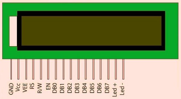
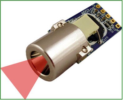
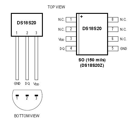
And an animated GIF image showing brightness tracking done with this camera in Processing.The first thing to do before you start is to create a suitable connector for the camera (after opening the cartridge structured box with a tri-wing screwdriver and disconnecting / removing the camera from the main structure). I attached a picture of the pinout, so many people used this image, so I don’t know who to give the credit (here’s one http://www.seattlerobotics.org/encoder/200205/gbcam.html). I used an IDC-10 connector to connect it to my old PIC board (from another project).In the next step we’ll be looking at the schematics and how the system actually functions.

Step 2

schematics and how the system actually functions

This is the card connected to my old PIC board. Since I had one laying around, I just made an expansion card to it for this project.
PORTC of the PIC is used for communicating with the camera, PORTD is dedicated to the 8-bit ADC output, and PORTB is used for the ADC’s CS and servos, which I didn’t really manage to control at that time (I tried observing pixel values on the fly, finding the brightest first pixel’s coordinates with a small formula, and adjusting the servo angles in accordance). Servos just went crazy, and I lost patience 😐

The LED’s are for displaying board power and frame capture. The schematics are a bit tangled since I didn’t care much about pin labeling then (to quickly create the PCB), so please have patience. I’m not going to attach the PIC board schematic and PCB files (but please pay attention to the pictures for pin orientation), since it’s basically a 40-pin PIC board with a crystal, and all the ports are connected to IDC-10 connectors.

The pinout of the M6428FN connector in the schematic is as follows, so you can make a simpler adapter / connector for the camera as you see in the picture:

1- GND

2- Vout to ADC (Image data in analog)

3- Bit-bang XCK for SIN, RESET, LOAD, and START (and 10 KHz PWM with 50% DC to get the pixel values), also triggers ADC
conversion for each pixel value (74HC14 inverts this signal for the ADC to start the conversion), after a successfull read, ADC sends and interrupt to the PIC, and the PIC sends the digital value to its USART, which finally goes to our PC.

4- LOAD signal to camera (Parameter Register Set Enable)

5- START signal to camera (Start Image Sensing)

6- VCC (all the analog and digital power)

7- SIN signal to write the regs on the camera (Parameter Data Input)

8- RESET signal to camera (Reset Parameter Registers)

9- READ (Image) signal from camera

10- GND

For more info on these pins, please refer to the image sensor datasheet attached on the next steps. You’ll understand the schematics better when you read the comments in the code files.

For more detail: PC Interfacing a GameBoy Camera using PIC18F4620 microcontroller

Current Project / Post can also be found using:

  • program on games in pic 16f877a

The post PC Interfacing a GameBoy Camera using PIC18F4620 microcontroller appeared first on PIC Microcontroller.

Interfacing of PIC16F84A with DS1307 (RTC) code and Proteus simulation

$
0
0

This post provides the code for interfacing DS1307 RTC with PIC16F84A microcontroller. This DS1307 RTC has i2c based interface and PIC16F84A doesn’t have any built in i2c modules, so software i2c module is created in the code. This code is written in C language using MPLAB with HI-TECH C compiler. You can download this code from the ‘Downloads‘ section at the bottom of this page.

Interfacing of PIC16F84A with DS1307

It is assumed that you know how to interface LCD with PIC16F84A microcontroller in 4bit mode. If you don’t then please read this page first, before proceeding with this article. It is also assumed that you know how to create software i2c module in PIC16F84A, if you don’t then please read this page first.

The result of simulating the code in Proteus is shown below.

In the above circuit[1], RA4 pin is being used as SDA pin and RB0 pin is the SCK pin. Both of these pins are pulled up using 10K resistors as required for i2c protocol. DS1307 RTC is the slave device, while PIC16F84A is configured to be the master. LCD is also attached with PIC16F84A, just to show the values received from the RTC, otherwise it is not required in this circuit. Proteus provides an ‘I2C Debugger Tool‘ which is attached on the SDA and SCK pins in the above circuit, this debugger shows all the activity on i2c bus[2]. It is attached in the circuit just for debugging purposes.

In the code, in the start a command is sent to DS1307 to set time to 8:32:59 AM and date to 2/11/12. After this, DS1307 starts to increment it’s time after every second. Then new time is read from DS1307 RTC after every second and displayed on the LCD. Figure 1 was taken when time was 8:33:22 AM, which is correctly displayed on the LCD.

Interfacing of PIC16F84A with DS1307 schematic

Code

The code for the main function is shown below.

In the main function, firstly LCD is initialized using InitLCD() function. Then i2c pins are initialized using InitI2C() function. Then using Set_DS1307_RTC_Time(AM_Time, 8, 32, 59) function, a command is sent to DS1307 to set it’s time to 8:32:59 AM. After that, Set_DS1307_RTC_Date(2, 11, 12, Friday) command sets DS1307 date registers to 2/11/12 @ Friday date.

Downloads

DS1307 RTC interfacing with PIC16F84A code was compiled in MPLAB v8.85 with HI-TECH C v9.83 compiler and simulation was made in Proteus v7.10. To download code and Proteus simulation click here.


For more detail: Interfacing of PIC16F84A with DS1307 (RTC) code and Proteus simulation

The post Interfacing of PIC16F84A with DS1307 (RTC) code and Proteus simulation appeared first on PIC Microcontroller.

Viewing all 111 articles
Browse latest View live


<script src="https://jsc.adskeeper.com/r/s/rssing.com.1596347.js" async> </script>