Quantcast
Channel: interfacing | Battery Guide
Viewing all 111 articles
Browse latest View live

PIC12F675 LCD Interfacing Code and Proteus Simulation

$
0
0

This post provides the LCD[1] interfacing code using PIC12F675 microcontroller. This code is written in C language using MPLAB with HI-TECH C compiler. You can download this code from the ‘Downloads‘ section at the bottom of this page.

PIC12F675 LCD Interfacing

It is assumed that you know how to make an LED blink with PIC12F675 microcontroller. If you don’t then please read this page first, before proceeding with this article.

PIC12F675 microcontroller has only 6 IO pins ( 5 of them can be made input or output, but pin4 (GP3) can only be made an input ). So it is not possible to directly attach LCD with PIC12F675 even in 4bit mode[2]. To make this possible, a serial to parallel shift register IC (4094) is used in this circuit. In this way by only using 3 pins of PIC12F675 microcontroller, we can interface LCD with it in 4bit mode. This is shown below in the figure.

In the above figure, GP0 pin is being used as Enable pin for LCD. GP1 pin is used as Clock pin and GP2 pin is used as Data pin for 4094 IC.

PIC12F675 LCD Interfacing schematic

Code

In the code you can easily select pins to be used for interfacing with the LCD. Following figure shows the pin selection code.

Downloads

LCD interfacing code using PIC12F675 was compiled in MPLAB v8.85 with HI-TECH C v9.83 compiler and simulation was made in Proteus v7.10. To download code and Proteus simulation click here.


For more detail: PIC12F675 LCD Interfacing Code and Proteus Simulation

Current Project / Post can also be found using:

  • pic12f675 code
  • rs232 lcd proteus
  • lcd in proteus

The post PIC12F675 LCD Interfacing Code and Proteus Simulation appeared first on PIC Microcontroller.


Matrix Keypad interfacing with PIC microcontroller.

$
0
0

Matrix keypads are very useful when designing certain systems which needs user input. These keypads are constructed by arranging push button switches in rows and columns as shown in Fig.1. Scanning keypad to detect pressed keys involves several steps and there are several methods to achieve this. The method presented here is capable of detecting more that one key press at time and encode that information in single 16bit (unsigned int) variable. For example this keypad scan routine can be used to detect key presses like CTRL+C in computer keypads.

The example program given in this page uses schematic diagram shown and uses Microchip C18 compiler. The example program will display number of key pressed in 7 segment LED display. If more than one key pressed at a time, it will display ‘H’ character. Schematic diagram shown also shows ICD2 connection which is optional and you can use any programmer/debugger to upload this program to PIC.Matrix Keypad interfacing with PIC microcontroller

Example program has function “ unsigned int ScanKeypad(void) ” where you can use this in your codes provided that keypad is connected to PICs pins as given in schematic bellow.

Keypad Scan Algorithm.

Scanning any matrix keypad involves several steps. The operation algorithm of example ScanKeypad(void) routine given here is explained in following steps. This routine uses logic operations instead of assigning values to ports because we can change only necessary pins while not touching unused pin values. This is very useful when you have other IP or OP devices connected to remaining pins of same port used by keypad. i.e. PORTB4:7 and PORTD0:3 in this example. ScanKeypad(void) routine should be called only after setting ROW pins and OP and Column pins as IP from main program via setting and clearing appropriate TRIS bits (shown in example code).

1. ScanKeypad(void) routine supply logic 0 (0V or GND) to all 4 keypad row wires named R1, R2, R3 and R4 in schematic diagram.(Assume that no key is pressed and since all columns has 1k pull down resisters connected as in schematic diagram. This will cause PICs PORTB0:3 pins to read logic 0 if we read them)

2. Next ScanKeypad(void) will set RD4 (ROW1) pin to Logic High (5V). Now if one or more key from keypad ROW1 pressed, Logic High will be passed through respective switch to PICs respective PORTB0:3 inputs. Pressing keys from any other row will not have any effect on this because these rows have logic 0.

3. Now we read all 4 columns (PORTB0:3) at once and get that data in to unsigned int variable. Since we read only 4 bits, these bits will be recorded in bits 0 to 3 in keys variable. Other 12 bits of keys variable will be set to 0. If any switch belongs to row one pressed, that respective bit will be set.

4. Now we shift least significant 4 bits with row 1 keypad data in keys variable to most significant 4 bits of keys variable in ScanKeypad(void) routine. i.e. shift keys bits 0:3 to keys bits 12:15.

5. Next make ROW1 (RD4) logic 0 and ROW2 (RD5) logic1. Read PORTB0:3 and get result tin to unsigned int keys_tmp variable. Then shift result left by 8 and position row2 data acquired in to keys_tmp bits 8:11. Then combine (bit wise OR) keys and keys_tmp variables in to keys variable. Now we have row1 and row 2 switch status in keys variable bits 8:15.Matrix Keypad interfacing with PIC microcontroller schematic

6. Repeat 5 for column 3 with respective modifications, (refer example code) and take row 3 key status in to keys variable bits 4:7. Now we have rows 1,2 and 3 data in keys bits 4:15

7. Repeat 5 for column 4 with respective modifications, (refer example code).

8. Now we have status of all 16 keys in variable keys and return that variable from ScanKeypad() routine

9. If we have at least one key pressed, then return from ScanKeypad()  will be non zero.

10. If we get non zero value from ScanKeypad(), we should de-bounce keypad and identify really pressed keys and process them as required.


For more detail: Matrix Keypad interfacing with PIC microcontroller.

Current Project / Post can also be found using:

  • multiplexing uses pic keypad

The post Matrix Keypad interfacing with PIC microcontroller. appeared first on PIC Microcontroller.

Interfacing of PIC12F675 with (i2c based) 24LC64 EEPROM (code + Proteus simulation)

$
0
0

This post provides the code for interfacing 24LC64 EEPROM with PIC12F675 microcontroller. This 24LC64 EEPROM has i2c based interface and PIC12F675 doesn’t have any built in i2c modules, so software i2c module is created in the code. This code is written in C language using MPLAB with HI-TECH C compiler. You can download this code from the ‘Downloads‘ section at the bottom of this page.

Interfacing of PIC12F675 with (i2c based) 24LC64 EEPROM
It is assumed that you know how to interface LCD with PIC12F675 microcontroller. If you don’t then please read this page first, before proceeding with this article. It is also assumed that you know how to create software i2c module in PIC12F675, if you don’t then please read this page first. You should also read how to write/read a byte in/from 24LC64 EEPROM from it’s datasheet.

The result of simulating the code in Proteus is shown below.

In the above circuit[1], GP4 pin is being used as SDA pin and GP5 pin is the SCK pin. Both of these pins are pulled up using 10K resistors as required for i2c protocol. 24LC64 EEPROM is the slave device, while PIC12F675 is configured to be the master. LCD is also attached with PIC12F675, just to show the values received from the EEPROM, otherwise it is not required in this circuit. Proteus provides an ‘I2C Debugger Tool‘ which is attached on the SDA and SCK pins in the above circuit, this debugger shows all the activity on i2c bus[2]. It is attached in the circuit just for debugging purposes.

In the code, string ‘Saeed’ is stored in the 24LC64 EEPROM and then retrieved back and displayed on the LCD. As shown in Figure 1, ‘Saeed‘ is correctly displayed on the LCD, this shows that it was stored and retrieved from 24LC64 EEPROM successfully.

Interfacing of PIC12F675 with (i2c based) 24LC64 EEPROM  schematic

Code

The code for the main function is shown below.

In the main function, firstly ADC and comparator are turned off to make pins digital IO pins instead of analog pins using InitCCT() function. Then LCD is initialized using InitLCD() function. Then i2c pins are initialized using InitI2C() function. Then Write_Byte_To_24LC64_EEPROM(0x0001, ‘d’); function writes 0x64 (i-e ‘d’) value on 0x0001 address in the EEPROM. After that, Read_Byte_From_24LC64_EEPROM(0x0001); function reads a single byte from 0x0001 address and saves this value in RxByte variable.

Write_Page_To_24LC64_EEPROM(0x0020, TxArray, 4); function writes 4 bytes present in the TxArray starting from address 0x0020. And Read_Bytes_From_24LC64_EEPROM(0x0020, RxArray, 4); function  reads 4 bytes from the starting address of 0x0020 and saves these bytes in RxArray. In the end all of these 5 received bytes are displayed on the LCD. You can verify from Figure 1, that all of these bytes were correctly received and displayed on the LCD. Using these simple read and write functions you can easily interface 24LC64 EEPROM with PIC12F675.

Downloads

24LC64 EEPROM interfacing with PIC12F675 code was compiled in MPLAB v8.85 with HI-TECH C v9.83 compiler and simulation was made in Proteus v7.10. To download code and Proteus simulation click here.


For more detail: Interfacing of PIC12F675 with (i2c based) 24LC64 EEPROM (code and Proteus simulation)

Current Project / Post can also be found using:

  • address of eeprom in proteus for i2c

The post Interfacing of PIC12F675 with (i2c based) 24LC64 EEPROM (code + Proteus simulation) appeared first on PIC Microcontroller.

Lab 4: Interfacing a character LCD using PIC16F688

$
0
0

Description

HD44780 based LCD displays are very popular among hobbyists because they are cheap and they can display characters. Besides they are very easy to interface with microcontrollers and most of the present day high-level compilers have in-built library routines for them. Today, we will see how to interface an HD44780 based character LCD to a PIC16F688 microcontroller. The interface requires 6 I/O lines of the PIC16F688 microcontroller: 4 data lines and 2 control lines. A blinking test message, “Welcome to Embedded-Lab.com”, will be displayed on the LCD screen.

character LCD

Required Theory

All HD44780 based character LCD displays are connected through 14 pins: 8 data pins (D0-D7), 3 control pins (RS, E, R/W), and three power lines (Vdd, Vss, Vee). Some LCDs have LED backlight feature that helps to read the data on the display during low illumination conditions. So they have two additional connections (LED+ and LED-), making altogether 16 pin. A 16-pin LCD module with its pin diagraam is shown below.

Control pins
The control pin RS determines if the data transfer between the LCD module and an external microcontroller are actual character data or command/status. When the microcontroller needs to send commands to LCD or to read the LCD status, it must be pulled low. Similarly, this must be pulled high if character data is to be sent to and from the LCD module.

The direction of data transfer is controlled by the R/W pin. If it is pulled Low, the commands or character data is written to the LCD module. And, when it is pulled high, the character data or status information from the LCD registers is read. Here, we will use one way data transfer, i.e., from microcontroller to LCD module, so the R/W pin will be grounded permanently.

The enable pin (E) initiates the actual data transfer. When writing to the LCD display, the data is transferred only on the high to low transition of the E pin.

Power supply pins
Although most of the LCD module data sheets recommend +5V d.c. supply for operation, some LCDs may work well for a wider range (3.0 to 5.5 V). The Vdd pin should be connected to the positive power supply and Vss to ground. Pin 3 is Vee, which is used to adjust the contrast of the display. In most of the cases, this pin is connected to a voltage between 0 and 2V by using a preset potentiometer.

Data pins
Pins 7 to 14 are data lines (D0-D7). Data transfer to and from the display can be achieved either in 8-bit or 4-bit mode. The 8-bit mode uses all eight data lines to transfer a byte, whereas, in a 4-bit mode, a byte is transferred as two 4-bit nibbles. In the later case, only the upper 4 data lines (D4-D7) are used. This technique is beneficial as this saves 4 input/output pins of microcontroller. We will use the 4-bit mode.

For further details on LCDs, I recommend to read these two articles first from Everyday Practical Electronics magazine : How to use intelligent LCDs Part 1, and Part 2.

Circuit Diagram

Data transfer between the MCU and the LCD module will occur in the 4-bit mode. The R/W pin (5) of the LCD module is permanently grounded as there won’t be any data read from the LCD module. RC0-RC3 serves the 4-bit data lines (D4-D7, pins 11-14) of the LCD module. Control lines, RS and E, are connected to RC4 and RC5. Thus, altogether 6 I/O pins of the PIC16F688 microcontrollers are used by the LCD module. The contrast adjustment is done with a 5K potentiometer as shown below. If your LCD module has backlight LED, use a 68Ω resistance in series with the pin 15 or 16 to limit the current through the LED. The detail of the circuit diagram is shown below.


For more detail: Lab 4: Interfacing a character LCD using PIC16F688

The post Lab 4: Interfacing a character LCD using PIC16F688 appeared first on PIC Microcontroller.

Interfacing Relay to Microcontroller

$
0
0

Figure 1 shows the basic relay driver circuit. As you can see an NPN transistor BC547 is being used to control the relay. The transistor is driven into saturation (turned ON) when a LOGIC 1 is written on the PORT PIN thus turning ON the relay. The relay is turned OFF by writing LOGIC 0 on the port pin. A diode (1N4007/1N4148) is connected across the relay coil; this is done so as to protect the transistor from damage due to the BACK EMF generated in the relay’s inductive coil when the transistor is turned OFF. When the transistor is switched OFF the energy stored in the inductor is dissipated through the diode & the internal resistance of the relay coil. Normally 1N4148 can be used as it is fast switching diode with a maximum forward current of 300ma. This diode is also called as free-wheeling diode.

Interfacing Relay to Microcontroller SchematicThe LED is used to indicate that the RELAY has been turned ON. The resistor R1 defines the current flowing through the LED thereby defining the LED’s intensity.

Resistor R2 is used as a Series Base Resistor to set the base current. When working with 8051 controllers I have noted that it’s not compulsory to use this resistor as the controller has internal 10k resistor which acts as a base resistor.

Microcontrollers have internal pull up resistors hence when a port pin is HIGH the output current flows through this internal pull up resistor. 8051 microcontrollers have an internal pull up of 10KΩ. Hence the maximum output current will be  5v/10k = 0.5ma. This current is not sufficient to drive the transistor into saturation and turn ON the relay. Hence an external pull up resistor R3 is used. Let us now calculate the value of R3.

Interfacing Relay to Microcontroller SchematicNormally a relay requires a pull in current of 70ma to be turned ON. So our BC547 transistor will require enough base current to make sure it remains saturated and provide the necessary collector current i.e. 70ma. The gain (hfe) of BC547 is 100 so we need to provide at least   70ma/100 = 0.7ma  of base current. In practice you require roughly double the value of this current so we will calculate for 1.4ma of base current.


For more detail: Interfacing Relay to Microcontroller Schematic

Current Project / Post can also be found using:

  • 5 pin 24vdc relay
  • transistor 548

The post Interfacing Relay to Microcontroller appeared first on PIC Microcontroller.

Lecture 43 : Interfacing PIC16F877 Microcontroller with an LCD

$
0
0
Aim

To interface LCD (Displaytech 162A) with PIC16F877microcontroller and to display “IITK” in the Liquid Crystal Display (LCD).

Components/Softwares
  1. MPLAB IDE (PIC microcontrollers simulator)
  2. PIC BURNER 3 with software to load the code
  3. LCD (Displaytech 162A)
  4. Computer System with Windows operating system and RS 232 cable
  5. PIC16F877 Microcontroller

Lecture 43  Interfacing PIC16F877 Microcontroller with an LCD

  1. +5V D.C Power Supply
  2. Resistors – 10K Ω-1,50Ω-1
  3. Capacitors – 27 µ F-2
  4. Potentiometers – 10K Ω -1
  5. 20MHz Crystal oscillator
  6. SPST switches -1
Procedure
  1. Write the assembly code in MPLAB IDE simulator , compile it and check for errors
  2. Once the code was error free, run it and check the output in the simulator.
  3. After checking the code in the simulator, load the code (in .HEX format) into PIC16F877 microcontroller using PIC BURNER3.
  4. Make connections as shown in the circuit diagram.
  5. Switch on the power supply and observe “IITK” displayed in the LCD.

Liquid Crystal Display (LCD-Displaytech 162A )LCD Displaytech 162A consists of a LCD panel, a controller IC (KS0070B) and a back light LED. The LCD module consists of total 16 pins in which, 2 are for power supply, 2 pins for Backlight LED, one pin for contrast adjustment, 3 pins are for control signals and 8 pins are data pins. In order to display any data, we need to do certain initiations. The following are the main three steps in displaying any data in the LCD display.

Lecture 43  Interfacing PIC16F877 Microcontroller with an LCD Schematic

  1. Initializing LCD by sequence of instructions
  2. Executing commands depending on our settings in the LCD
  3. Writing data into the DRAM locations of LCD in the Standard Character Pattern of LCD

For doing above steps, refer the manual for LCD and follow the instructions and timing diagrams strictly.
MPLABIDEMPLABIDE is a free software which can be downloaded from the website www.microchip.com
Working with MPLABIDE :
MPLABIDE is a simulator for PIC microcontrollers to write and edit the code in assembly language, compile it and also to run the code. Output can be verified using simulator.


For more detail: Lecture 43  Interfacing PIC16F877 Microcontroller with an LCD

The post Lecture 43 : Interfacing PIC16F877 Microcontroller with an LCD appeared first on PIC Microcontroller.

Major Electronic Peripherals Interfacing to Microcontroller 8051

$
0
0

Interfacing is one of the important concepts in microcontroller 8051 because the microcontroller is a CPU that can perform some operation on a data and gives the output. However to perform the operation we need an input device to enter the data and in turn output device displays the results of the operation. Here we are using keyboard and LCD display as input and output devices along with the microcontroller.

Interfacing is the process of connecting devices together so that they can exchange the information and that proves to be easier to write the programs. There are different type of input and output devices as for our requirement such as LEDs, LCDs, 7segment, keypad, motors and other devices.

Here is given some important modules interfaced with microcontroller 8051.

Major Electronic Peripherals Interfacing to Microcontroller 80511. LED Interfacing to Microcontroller:

Description:

LEDs are most commonly used in many applications for indicating the output. They find huge range of applications as indicators during test to check the validity of results at different stages. They are very cheap and easily available in a variety of shape, color and size.

The principle of operation of LEDs is very easy. A simple LEDs also servers as a basic display devices, it On and OFF state express meaning full information about a device. The common available LEDs have a 1.7v voltage drop that means when we apply above 1.7V, the diode conducts. The diode needs 10mA current to glow with full intensity.

The following circuit describes “how to glow the LEDs”.

LEDs can be interfaced to the microcontroller in either common anode or common cathode configuration. Here the LEDs are connected in common anode configuration because the common cathode configuration consumes more power.

Source code:

#include<reg51.h>
void main()
{
unsigned int i;
while(1)
{
P0=0x00;
for(i=0;i<30000;i++);
P0=0xff;
for(i=0;i<30000;i++);}}

2. 7-Segment Display interfacing circuit

Description:
A Seven segment display is the most basic electronic display. It consists of eight LEDs which are associated in a sequence manner so as to display digits from 0 to 9 when proper combinations of LEDs are switched on. A 7-segment display uses seven LEDs to display digits from 0 to 9 and the 8th LED is used for dot.

The 7-segment displays are used in a number of systems to display the numeric information. They can display one digit at a time. Thus the number of segments used depends on the number of digits to display. Here the digits 0 to 9 are displayed continuously at a predefined time delay.

The 7-segment displays are available in two configurations which are common anode and common cathode. Here common anode configuration is used because output current of the microcontroller is not sufficient enough to drive the LEDs. The 7-segment display works on negative logic, we have to provide logic 0 to the corresponding pin to make on LED glow.

Source Code:

#include<reg51.h>
sbit a= P3^0;
void main()
{
unsigned char n[10]= {0x40,0xF9,0x24,0x30,0x19,0x12,0x02,0xF8,0xE00,0x10};
unsigned int i,j;
a=1;
while(1)
{
for(i=0;i<10;i++)
{
P2=n[i];
for(j=0;j<60000;j++);
}
}
}

3. LCD Interfacing to Microcontroller

LCD stands for liquid crystal display which can display the characters per line. Here 16 by 2 LCD display can display 16 characters per line and there are 2 lines. In this LCD each character is displayed in 5*7 pixel matrix.

LCD is very important device which is used for almost all automated devices such as washing machines, an autonomous robot, power control systems and other devices. This is achieved by displaying their status on small display modules like 7-seven segment displays, multi segment LEDs etc. The reasons being, LCDs are reasonably priced, easily programmable and they have a no limitations of displaying special characters.

It consists of two registers such as command/instruction register and data register.

The command/instruction register stores the command instructions given to the LCD. A command is an instruction which is given to the LCD that perform a set of predefined tasks like initializing, clearing the screen, setting the cursor posing, controlling display etc.

The data register stores the data to be displayed on LCD. The data is an ASCII value of the characters to be displayed on the LCD.

Operation of LCD is controlled by two commands. When RS=0, R/W=1 it reads the data and when RS=1, R/W=0, it writes (print) the data.

Source code:

#include<reg51.h>
#define kam P0

sbit rs= P2^0;
sbit rw= P2^1;
sbit en= P2^2;

Major Electronic Peripherals Interfacing to Microcontroller 8051 Schematicvoid lcd_initi();
void lcd_dat(unsigned char );
void lcd_cmd (unsigned char );
void delay(unsigned int );
void display(unsigned char *s, unsigned char r);
void main()
{lcd_initi();
lcd_cmd(0x80);
delay(100);
display(“EDGEFX TECHLNGS”, 15);

lcd_cmd(0xc0);display(“KITS & SOLTIONS”,15);
while(1);}void display(unsigned char *s, unsigned char r)
{unsigned int w;
for(w=0;w<r;w++)
{lcd_dat(s[w]);}}

void lcd_initi(){lcd_cmd(0x01);delay(100);lcd_cmd(0x38);
delay(100);lcd_cmd(0x06);delay(100);
lcd_cmd(0x0c);delay(100);}
void lcd_dat(unsigned char dat)
{kam = dat;
rs=1;
rw=0;

en=1;
delay(100);
en=0;}void lcd_cmd(unsigned char cmd)
{kam=cmd;rs=0;rw=0;en=1;
delay(100);en=0;}
void delay( unsigned int n)
{unsigned int a;
for(a=0;a<n;a++);}


For more detail: Major Electronic Peripherals Interfacing to Microcontroller 8051

The post Major Electronic Peripherals Interfacing to Microcontroller 8051 appeared first on PIC Microcontroller.

Interfacing DS1307 to PIC Microcontroller with C code and Circuit Diagram

$
0
0
This tutorial will help you to interface DS1307 RTC with PIC16F877 Microcontroller. The project is compiled in CCS Compiler and simulated with Proteus. The Real Time Clock is interfaced with PIC controller via I2C. I2C is a 2 wire communication protocol. I2C is used for moving data from one device to another simply and quickly. It is a serial, synchronous, Bi-Directional protocol, the data is synchronised  with clock through SCL pin and it controls when data is changed and when it should be read. All device is controlled by master device’s clock, No data is transferred in the absence of clock.
As mentioned above data is bi-directional, master device can both transmit and receive data. The serial data (SDA) and Serial Clock (SCL) pins must be pulled up with resistors, the value of resistors determine the speed of communication.
Interfacing DS1307 to PIC Microcontroller with C code and Circuit DiagramEmbedded C Program for DS-1307 I2C Communication
#include <16F877.h>
#include <lcd_4bit.c>
#use delay(clock=4000000)
#define RTC_SDA  PIN_C4
#define RTC_SCL  PIN_C3
#use i2c(master, sda=RTC_SDA, scl=RTC_SCL)
void rtc_get_time() ;
int convert(int k);
int sec,min,hr,k[20],z,k1[20];
int day1,date,month,year;
void main()
{SETUP_ADC(ADC_OFF);
lcd_init();
while(1)
{rtc_get_time();
lcd_cmd(0x80);
sprintf(k,”%02d:%02d:%02d”,hr,min,sec);
lcd_array(k);
lcd_cmd(0xc0);
sprintf(k1,”%02d:%02d:%02d “,date,month,year,);
lcd_array(k1);
lcd_cmd(0xc9);
switch(day1)
{
case 1: lcd_str(“Sunday”);
break;
case 2: lcd_str(“Monday”);
break;
case 3: lcd_str(“Tuesday”);
break;
case 4: lcd_str(“Wednesday”);
break;
case 5: lcd_str(“Thursday”);
break;
case 6: lcd_str(“Friday”);
break;
case 7: lcd_str(“Saturday”);
break;
} }}
void rtc_get_time()
{
  i2c_start();
  i2c_write(0xD0);
  i2c_write(0x00);
  i2c_start();
  i2c_write(0xD1);
  sec = i2c_read();
  min = i2c_read();
  hr  = i2c_read();
 day1=i2c_read();
 date=i2c_read();
 month=i2c_read();
 year=i2c_read(0);
  i2c_stop();
 Interfacing DS1307 to PIC Microcontroller with C code and Circuit Diagram
 sec= convert(sec);
 min= convert(min);
 hr= convert(hr);
 day1= convert(day1);
 date= convert(date);
 month= convert(month);
 year= convert(year);
 z=’a’;
if(hr>12)
{
hr=hr-12;
z=’p’;
}
}
int convert(int k)
{
int a0,a1,a;
 a0=((k&0x0F));
 a1=k>>4;
  a=((a1*10)+a0);
  return a;
}
Above shows  a simple program to read the Time value from DS-1307 IC. RTC Ds-1307 consumes very low power(500nA), so it can be backup by a battery for power failure issues.   For DS1307, the device address is D0. The data, for example seconds value, located in the zeroth register is taken and converted from BCD to integer, before displaying it on the LCD. We can also write the Time value to Ds1307 registers one by one.

The post Interfacing DS1307 to PIC Microcontroller with C code and Circuit Diagram appeared first on PIC Microcontroller.


Interfacing with UART of PIC microcontroller

$
0
0

This post provides the solution for using the PIC controller UART interface (e-g to connect PIC controller with PC using serial adapter).

Interfacing with UART of PIC microcontroller

Complete code and simulation can be downloaded from the ‘Downloads‘ section at the bottom of this post. The following figure shows the result of simulation of PIC UART in Proteus7.6.

In the main function UART is intialized by calling the function InitUART (defined in the serial.c file included in the project). Then a Hello World! is sent on the UART terminal (e-g using serial adapter you can display this Hello World! on Hyper Terminal on PC). After that, interrupts are enabled because in the Interrupt Service Routine (ISR) UART interrupt is handled as shown below in the code.

Interfacing with UART of PIC microcontroller schematic

Downloads

The code was compiled in MPLAB v8.76 with HI-TECH C and simulation was made in Proteus v7.6.
To download code click here.
To download Proteus simulation click here.


For more detail: Interfacing with UART of PIC microcontroller

The post Interfacing with UART of PIC microcontroller appeared first on PIC Microcontroller.

Interfacing16X2 LCD with PIC Microcontroller

$
0
0

In this session we will see how to interface 16×2 LCD to PIC18F4550 microcontroller which is of family PIC18F. You can get information of 16×2 LCD in the session How to Interface 16X2 LCD with 8051 Microcontroller

Features of PIC18F4550:

  • PIC18F4550 belongs to the PIC18F family; PIC18F4550 is an 8bit microcontroller and uses RISC architecture. PIC18F4550 has 40 pins in PDIP (dual in line package) and 44 pin in TQFP (Quad flat package).
  • 32KB flash memory, 2048 bytes of SRAM (synchronous Random Access memory), EEPROM (Electrically Erasable Program Read Only Memory) of 256 bytes are embedded in the PIC18F4550.
  • It has 35 I/O pins for interfacing and communication with other peripherals, 13channel of 10bit analog to digital converters which are used for interfacing and communicating the analog peripherals (DC motor, LDR, etc.).

Interfacing16X2 LCD with PIC MicrocontrollerIt has 2 CCP and 1 ECCP module that is enhanced capture and compare module which is mainly used for modulation and waveform generation functions. CCP module is of 16bit register works as 16 capture bit register, 16 compare bit register, and PWM and duty cycle register.

  • PIC18F4550 has SPI (serial peripheral interface) and i2c (inter integrated circuit) for master and slave modes. It has SPP (Streaming Parallel Port) for USB streaming transfer.
  • PIC18F4550 is embedded with 4 timer modules (timer0 to timer3), 2 comparator modules and 3 external interrupt. It has Dual Oscillator options allow microcontroller and USB module to run at different clock speeds. It can operate in 2.0V to 5.5V

16X2 LCD Interfacing PIC Microcontroller – Circuit Explanation:

The resistor R1 is used for giving the contrast to the LCD. The crystal oscillator of 12 MHz is connected to the OSC1 and OSC2 pins of Pic microcontroller PIC18F4550 for system clock. The capacitor C2 and C3 will act filters to the crystal oscillator. You can use different ports or pins for interfacing the LCD before going to different ports please check the data sheet whether the pins for general purpose or they are special function pins.

Programming PIC for Interfacing 16X2 LCD:

Interfacing LCD to PIC is not different from interfacing to 8051. The basic concept and gist of the programming is almost same. Visit the following link for more information http://www.electronicshub.org/interfacing-16×2-lcd-8051/.

Only the pins, registers and architecture using for interfacing will be different. When we look at the program, functions like initialization, sending data to the LCD will be almost same.

In the pic programming also for initializing the LCD the R/W pin should be low for writing the data, Enable pins should be high and register select pin (RS) should be high for writing the data. For sending a command the RS should be low, R/W pin should be low and enable pin should be high.

Initializing the LCD function:

lcdcmd(0x38);//Configure the LCD in 8-bit mode,2 line and 5×7 font
lcdcmd(0x0C);// Display On and Cursor Off
lcdcmd(0x01);// Clear display screen
lcdcmd(0x06);// Increment cursor
lcdcmd(0x80);// Set cursor position to 1st line,1st column

Sending command to the LC:
  • rs=0;    Register select pin is low.                                                      
  • rw=0;  Read/write Pin is also for writing the command to the LCD.
  • en=1;enable pin is high.

Interfacing16X2 LCD with PIC Microcontroller schematicSending data to the LCD:

  • rs=1; Register select pin is high.
  • rw=0; Read/write Pin is also for writing the command to the LCD.
  • en=1; enable pin is high.
Steps for Programming:
  • Install MPLAB in your system and create a new project, in selecting device and family select PIC18F family and add PIC18F4550 controller to your project.
  • Select the compiler which you have installed and add the file to your project. After adding the file paste the code which is given below and run it. As it is a precompiled and tested program you will not find any errors.
  • After compiling the program with no errors dump the program into your development board using PICKIT2 or PICKIT3 programmer/ debugger.
  • If you are not using PICKIT then just compile the code and make the HEX file use this HEX file for programming the PIC microcontroller.


For more detail: Interfacing16X2 LCD with PIC Microcontroller

The post Interfacing16X2 LCD with PIC Microcontroller appeared first on PIC Microcontroller.

ESP8266 wifi module interfacing with pic microcontroller

$
0
0

ESP8266 wifi module interfacing with pic microcontroller: Hi everyone I hope you are fine and doing well. In this tutorial, I will guide you how to interface ESP8266 wifi module with pic microcontroller. We will be using pic18f46k22 microcontroller in this tutorial. I have seen many tutorials on internet on various websites related to interfacing of ESP8266 wifi module with Arduino But I have not found a single tutorial on how to interface ESP8266 wifi module with pic microcontroller. This module can be used to make internet of things based pic microcontroller projects. I have made a project on wifi based home automation system in which I also used esp8266 module. This module can be used in many applications. For example you can use it to send data to server and you can also use to control servo motor from website. It is very easy to interface this module with arduinobecause there are many resources available online related to Arduino. But in case of pic microcontroller you have to develop your library yourself.

ESP8266 wifi module configuration

So lets start with pin configuration of this module and how to connect this module with pic microcontroller. This module works on 3.3V voltage range. So make sure you do not connect more than 5 volt with this module otherwise your module will get damaged. It works on serial communication. I will further explain it in later part of this article.  This module has six pins as shown in picture below:

ESP826~1

Explanation of each pin along with their operating voltage range is given below.

  • Vcc pin: This pin is used to provide power supply. you should connect 3.3V with this pin and voltage more than 3.3 volt burns this wi-fi module.
  • GND pin: Connect ground terminal of power supply with this pin
  • RX pin: This is a receiver pin of ESP8266 wifi module. This module works on UART serial communication. So this pin is used to receive data from microcontroller or any other device to which you want to send data.
  • TX pin: This is a transmitter pin of ESP8266 wifi module. It is used to send or transmit data to microcontroller or any other device which works on serial communication principle.
  • GPIO_0 and GPIO_2 : These are general purpose input output pins which are used to directly interact with external digital world. This module can also be used as a stand along device to make IOT based projects. But I will not discuss this aspect in this article. I will write a separate article on it. But in today’s article, I will write only on how to interface ESP8266 wifi module with pic microcontroller.
  • RESET pin: It is used to reset this module. It is active high pin and it will reset the module when you apply 3.3 volt.
  • CH_PD pin:  Connect 3.3 volt of this pin.

So now you got basic understanding and pin configuration of this module. Now lets move to interfacing part that is how to interface esp8266 wifi module with pic microcontroller.

ESP8266 wifi module interfacing with pic microcontroller

To interface this module with any microcontroller and any digital device you should know about operating voltages of this device and microcontroller. As I mentioned earlier,  operating voltages of ESP8266 wifi module is 3.3 volt. So its transmission and receiver signal will be also be 3.3 volt amplitude.  So when you are connecting this module with any pic microcontroller, you need to make sure either both have same operating voltages or you need to connect any circuit with esp8266 and pic microcontroller.  This circuit should be cable of converting 3.3 volt signal to 5 volt and 5 volt signal to 3.3 volt.  you can also use voltage divider for this purpose. I will explain it in more details in coming paragraphs.

We are using pic18f46k22 pic microcontroller in this tutorial. Operating voltages of this pic microcontroller is 5 volt. So we need to use any circuit between ESP8266 wifi module and pic microcontroller. We can use a voltage divider between Tx pin of pic microcontroller and Rx pin of ESP8266 wifi module. Voltage divider will step down 5 volt signal of pic microcontroller transmitter to 3.3 volt which is in range of operating voltages of wifi module. We can connect transmit of wi-fi module directly with pic18f46k22 microcontroller, because this pic microcontroller have wide range of operating voltages between 3.3V and 5 volt. So there is not need of voltage divider between Rx pin of esp8266 and pic 18f46k22 microcontroller, because microcontroller will read 3.3 volt as a high signal. But we need to connect voltage divider between Tx pin of microcontroller and Rx pin of esp8266, Because wi-fi module can not read 5 volt and it will burn our module.  Interfacing connections are shown below:

ESP8266-wifi-module-interfacing-with-pic-microcontroller

As shown in above circuit diagram, we have connected 1k and 2k resistor between Tx pin of microcontroller and Rx pin of esp8266.  I assume you already familiar with voltage divider working principle. If you do not know, you can use a dedicated chip as 5 volt to 3.3 volt converter. Pic microcontroller and esp8266 wifi module communicate with each other through UART serial communication. So you should know how to use serial communication of pic microcontroller. ESP8266 wifi module responds to “AT” commands.  you should check data sheet of this module to know more about AT commands, you will send at commands to this wifi module from pic microcontroller through serial communication.  Before using AT commands you should set the Baud rate of this module to 9600 because by default baud rate of this wifi module is 115200.

AT+ UART_DEF = 9600, 8,1,0,0

This command is used to set baud rate of ESP8266 wifi module to 9600 permanently.  For more information on how to use AT commands check this video tutorial:

Read More Information….

ESP8266 wifi module interfacing with pic microcontroller

The post ESP8266 wifi module interfacing with pic microcontroller appeared first on PIC Microcontroller.

servo motor interfacing with 8051 using keil compiler

$
0
0

servo motor interfacing WITH 8051 MICROCONTROLLER: This article is about interfacing of servo motor with 8051 microcontroller. You will learn how to interface and control this motor using 8051 microcontroller. Servo motors are used in roboticsembedded systems and industries because they are very precise and reliable. They are used to operate remote control toy cars, airplanes or robots. Their motion can be controlled by rotating them in particular angle. Servo motor can be controlled by PWM signal. In this article we will interface servo motor with 8051 microcontroller and control its speed.  I will recommend you to read a article on how to used keil compiler and how to use I/O ports of 8051 microcontroller before learning about interfacing servo motor with 8051.

Page Contents
  • 1 CONSTRUCTION of servo motor
  • 2 PRINCIPLE of interfacing servo motor
  • 3 INTERFACING WITH 8051 MICROCONTROLLER
  • 4 CONNECTIONS diagram of servo motor interfacing with 8051 microcontroller
  • 5 PROTEUS SIMULATION of servo motor interfacing with 8051 microcontroller
  • 6 WORKING of servo motor interfacing with 8051 microcontroller
  • 7 CODE of servo motor interfacing with 8051 microcontroller
  • 8  APPLICATIONS OF SERVO MOTOR interfacing

CONSTRUCTION of servo motor

A DC servo motor consists of:

  • DC motor
  • Potentiometer (variable resistor)
  • Gear assembly
  • Control circuit

It consists of a closed loop system. Positive feedback is given to control the motion and position of the shaft. Feedback signal is generated by comparing output signal and reference input signal. Now, this feedback signal will act as input signal to control device. This signal will remain present as long as there remains a difference between reference input signal and output signal. So we have to maintain output of this system at desired value in presence of noises.

PRINCIPLE of interfacing servo motor

Servo motor is controlled by PWM (Pulse with Modulation) technique in which we control the angle of rotation through the duration of pulse applied to its Control pin.

It has three connection wires for:

  • Positive supply V+
  • Negative supply or Ground V-
  • Control signal

servo-motor-interfacing

First two wires are used for giving power to motor. The control signal is connected with microcontroller to feed PWM signals. Gear and potentiometer control the DC motor in it. Servo motor can turn to 90, 180 degree in either direction and can go up to 360 degrees. Turning angle depends on manufacturing. The servo motor expects a pulse after every 20ms. Length of pulse determines how far the motor turns. The shaft angle exceeds with increase of pulse width. The duration of that logic 1 pulse can be from 1ms to 2ms.

  • 1ms duration pulse can rotate servo motor to 0 degree
  • 5ms duration pulse can rotate it to 90 degree
  • 2ms duration pulse can rotate it to 180 degree

So we can say that pulse duration between 1ms to 2ms can rotate Servo motor to any angle that is between 0 and 180 degree.

rotate Servo motor

INTERFACING WITH 8051 MICROCONTROLLER

We will control servo motor with AT89C51 microcontroller. Servo motor red and black wires are connected to battery and ground respectively. Its control wire is connected with any port pin of microcontroller.

CIRCUIT COMPONENTS:

  • AT89C51 microcontroller
  • 12 MHz Oscillator
  • 5V DC battery
  • Servo motor
  • 2 Ceramic capacitors – 33pF
  • 300Ω resistors – 3
  • Push buttons – 3

CONNECTIONS diagram of servo motor interfacing with 8051 microcontroller

  • P2 of 8051 microcontroller is used as output port. Its lower one pin is used which is connected with control pin of servo to give logic input to servo motor.
  • P0 of 8051 microcontroller is used as output port. Its lower three pins are connected with push buttons so that we can manually start the motor.
  • 5V battery is used to give input to servo motor.

PROTEUS SIMULATION of servo motor interfacing with 8051 microcontroller

servo-motor-interfacing-with-8051-microcontroller

WORKING of servo motor interfacing with 8051 microcontroller

When we start the simulation, motor will not rotate until any button is pressed. When 1st push button is pressed, servo motor will rotate up to 90 degree. When I press 2nd push button, it can rotate up to 180 degree and stops. And when 3rd push button is pressed, it will rotate up to 270 degrees.

CODE of servo motor interfacing with 8051 microcontroller

#include <REGX51.H>

void Delay_servo(unsigned int);

sbit control_pin=P2^0;

sbit B1=P0^0;

sbit B2=P0^1;

sbit B3=P0^2;

void main()

{

P0=0x07;                                            // input port

control_pin=0;                                                 // output pin

do

{

if(B1==1)

{                                              //Turn to 90 degree

control_pin=1;

Delay_servo(1218);

control_pin=0;

}

else if(B2==1)

{                                               //Turn to 180 degree

control_pin=1;

Delay_servo(1470);

control_pin=0;

}

else if(B3==1)

{                                               //Turn to 270 degree

control_pin=1;

Delay_servo(1720);

control_pin=0;

}

}while(1);

}

void Delay_servo(unsigned int d)

{

TMOD &=0xF0;                    // Clear 4bit field for Timer0

TMOD|=0x01;                                   // Set timer0 in mode1, 16bit

TH0=0xFF – (d>>8)&0xFF;              // Load delay vales Timer 0 + Bitwise right shift[c][d]a >> b

TL0=0xFF- d&0xFF;

ET0=1;                                              //Enable timer0 interrupts

EA=0;                                                // Global Interrupt

TR0=1;                                              // Start timer 0

while(TF0==0);                                 // Wait for overflow

TR0=0;                                  //Stop timer0

TF0=0;                                              // Clear Flag

}

Read More Information….

servo motor interfacing with 8051 using keil compiler

The post servo motor interfacing with 8051 using keil compiler appeared first on PIC Microcontroller.

STEPPER MOTOR INTERFACING WITH 8051 MICROCONTROLLER

$
0
0

STEPPER MOTOR INTERFACING WITH 8051 MICROCONTROLLER: Stepper motors are type of DC motors. Stepper motor has multiple electromagnetic coils that are arranged in group called phases. Motor rotates when particular phase is energized. One step rotation occurs at a time by energizing a particular coil. We can also control the speed of motor. It can be interfaced with 8051 microcontroller but the same case is here about DC motors that we can’t connect them directly with controller. Here in this article we will learn how to interface stepper motor with 8051 microcontroller. Before starting this article you should know how to use keil for 8051 programmingand how to use input output ports of 8051 microcontroller.

Page Contents

  • 1 Stepper motor COMPARISON WITH DC MOTOR
  • 2 ADVANTAGES of stepper motor
  • 3 BASICS OF STEPPER MOTOR
  • 4 Stepper motor INTERFACING  WITH 8051 MICROCONTROLLER
  • 5 PROTEUS SIMULATION of stepper motor interfacing with 8051 microcontroller
  • 6 Working stepper motor interfacing with 8051 microcontroller
  • 7 CODE of stepper motor interfacing with 8051 microcontroller

Stepper motor COMPARISON WITH DC MOTOR

Unlike DC motors, the current consumption of stepper motors does not depend upon the load. Upon no load they still draw much current. In this way, they get hot and this lowers their efficiency. In stepper motors there is smaller torque at high speeds than at low speeds. But mostly these stepper motors are used in high speed routine. For obtaining that high speed performance they need to be paired with a proper driver.

ADVANTAGES of stepper motor

Stepper motors are used because of their:

  • Low cost
  • High reliability (because of no contact brushes)
  • Good performance in starting, stopping and reversing the direction
  • High torque at low speed
  • Gravel construction (can be used in variable environment)

BASICS OF STEPPER MOTOR

Stepper motor is brushless which take digital signals. It converts digital pulses into mechanical shaft rotation. Rotation is divided into steps and a separate pulse is sent for each step. For each pulse motor rotates a few degrees which is mostly 1.8 degree angle. As we interface it with controller, so when digital pulses increase in frequency, the stepping movement of motor converts to continuous rotation of motor. So we can say that speed of rotation is directly proportional to the frequency of pulses given by controller.

WINDING ARRANGEMENT:

For a two phase stepper motor, there are two winding arrangements of electromagnetic coils.

  • Unipolar
  • Bipolar

UNIPOLAR MOTOR:

  • Only one winding with center tap per phase
  • Each winding section is switched on for each direction of magnetic field
  • Center tap of each winding is made common

BIPOLAR MOTOR:

  • A single winding per phase
  • Current in winding must be reversed to reverse a magnetic pole
  • Two leads per phase, none are common

stepper-motor-with-8051-microcontroller

STEP MODES:

In this article we will use unipolar stepper motor. Unipolar stepper motors can be used in three modes:

  • Wave Drive mode
  • Full Drive mode
  • Half Drive mode

Wave Drive:

  • Only one electromagnet is energized at single time.
  • Torque which is generated will be less than full drive.
  • Power consumption is reduced in it.
  • This type of drive is chosen when the power consumption fact is more important than torque.

Full Drive:

  • Two electromagnets are energized at single time.
  • Torque which is generated will be greater than wave drive.
  • Power consumption is higher in it.
  • This type of drive is chosen when the torque is more important than power consumption.

Half Drive:

  • One and two electromagnets are alternatively energized in this mode.
  • It is a combination of both, wave drive and full drive.
  • It has low torque but the angular resolution is doubled.
  • This type of drive is chosen when we want to increase the angular resolution of the motor.

Since each drive has its own advantages and disadvantages, thus we choose the drive according to the application we want and power consumption.

Stepper motor INTERFACING  WITH 8051 MICROCONTROLLER

Due to high voltage and current limitations of microcontroller, a motor Driver IC is used. We can use L293D or ULN2003. Working of both is already described in previous articles.

CIRCUIT COMPONENTS:

  • AT89C51 microcontroller
  • 12 MHz Oscillator.
  • 12V DC battery.
  • 5V DC battery.
  • L293D motor driver
  • Unipolar Stepper motor – 1.
  • 2 Ceramic capacitors – 33pF
  • 300Ω resistors – 3
  • Push buttons – 3

CONNECTIONS:

  • P2 (Lower four pins) of 8051 microcontroller is used as output port and it gives inputs to the L293D (motor driver IC) to drive one stepper motor.
  • P0 (Lower three pins) of 8051 microcontroller is used as input port. 3 Buttons are connected to them so that we can manually start and stop the motor.
  • Stepper motor is given input through OUT1, OUT2, OUT3 and OUT4 of L293D.
  • 12V battery is used to give input to the VS for motor.
  • 5V battery is used to give input to VSS for motor driver IC.

PROTEUS SIMULATION of stepper motor interfacing with 8051 microcontroller

stepper-motor-interfacing-with-8051-microcontroller

Working stepper motor interfacing with 8051 microcontroller

I tried to use all three modes. When I press button 1, it works as wave drive. Only one electromagnet is energized at single time and in coding one pin is high at a time. When I open the switch/button, motor tends to stops and gets stop within few seconds.

Wave drive Stepping Sequence
Step # Pin 1 Pin 2 Pin 3 Pin4
1 1 O O 0
2 O 1 O O
3 O O 1 O
4 O O O 1

When I press button 2, it works as full drive. Two electromagnets are energized at single time and in coding one pin is high at a time. When I open the switch/button 2, motor tends to stops and gets stop within few seconds.

Full drive Stepping Sequence
Step # Pin 1 Pin 2 Pin 3 Pin4
1 1 1 O O
2 O 1 1 O
3 O O 1 1
4 1 O O 1

When I press button 3, it works as half drive. One and two electromagnets are alternatively energized at a single time and in coding:

  • First pin is high
  • Then first and second both get high
  • Second alone goes high
  • Second along with third goes high
  • In same way, alternatively one and two pins go high
Half drive Stepping Sequence
Step # Pin 1 Pin 2 Pin 3 Pin4
1 1 O O O
2 1 1 O O
3 O 1 O O
4 O 1 1 O
5 O O 1 O
6 O O 1 1
7 O O O 1
8 1 O O 1

When I open the switch/button, motor tends to stops and gets stop within few seconds.

CODE of stepper motor interfacing with 8051 microcontroller

#include<reg52.h>

void delay(int);

sbit B1 = P0^0;

sbit B2 = P0^1;

sbit B3 = P0^2;

void main()

{

P1=0x07;

P2=0x00;

if(B1==1)                                                             //for wave drive

{

P2=0x01; //0001

delay(1000);

P2=0x02; //0010

delay(1000);

P2=0x04; //0100

delay(1000);

P2=0x08; //1000

delay(1000);

}

if(B1==0)

{

P2=00000000;

}

if(B2==1)                                               //for full drive

{

P2 = 0x03; //0011

delay(1000);

P2 = 0x06; //0110

delay(1000);

P2 = 0x0C; //1100

delay(1000);

P2 = 0x09; //1001

delay(1000);

}

if(B2==0)

{

P2=00000000;

}

if(B3==1)                                             //for half drive

{

P2=0x01; //0001

delay(1000);

P2=0x03; //0011

delay(1000);

P2=0x02; //0010

delay(1000);

P2=0x06; //0110

delay(1000);

P2=0x04; //0100

delay(1000);

P2=0x0C; //1100

delay(1000);

P2=0x08; //1000

delay(1000);

P2=0x09; //1001

delay(1000);

}

if(B3==0)

{

P2=00000000;

}

}

void delay(int k)

{

int i,j;

for(i=0;i<k;i++)

{

for(j=0;j<100;j++)

{}

}

}

Read More Information..

The post STEPPER MOTOR INTERFACING WITH 8051 MICROCONTROLLER appeared first on PIC Microcontroller.

DC MOTOR INTERFACING WITH 8051 MICROCONTROLLER

$
0
0

DC MOTOR INTERFACING WITH 8051 MICROCONTROLLER: In many projects of embedded systems, we may need to control a DC motor using controller.  It is not good to connect DC motor directly to the microcontroller. Since the maximum current that can be sink from 8051 microcontroller is 15 mA at 5v. But a DC Motor needs much more currents. It also needs more voltages as 6v, 12v, 24v etc., (depending upon the type of motor used). One more thing to notice is that the back emf produced by the motor may affect the proper functioning of the microcontroller and reversing the direction can damage the controller. Due to these reasons we can’t connect a DC Motor directly to a microcontroller. This article will demonstrate how to control the DC motor using AT89C51 Microcontroller.

MOTOR DRIVER for dc motor interfacing with 8051 microcontrollerTo overcome the problems in their interfacing, a motor Driver IC is connected between microcontroller and DC motor. Motor driver is a little current amplifier. It takes a low current signal and gives out a high current signal which can drive a motor. It can also control the direction of motor. We can use any dual H-bridge IC like L293D or L298.

The main differences between L293D and L298 are:

CHARACTERISTICS L298 L293D
Max. output current per channel 2A 0.6A
Peak max. output current per channel 3A 1A
Protection diodes across motors Use externally Internally available

L298 motor driver is already explained in separate article. In this article, we will use L293D since it does not need external protection diodes.

H-bridge can also be made with the help of transistors and MOSFETs etc. It will be cheap but they increase the size of the design and circuit board which is mostly not required, so a small 16 pin IC is preferred for this purpose. Actually, the name “H-Bridge” is derived from the shape of the switching circuit which controls the motion of the motor. It is also known as “Full Bridge”. Basically there are four switching elements in the H-Bridge as shown in the figure below.

As we can see in the figure that there are four switching elements named as:

  • High side left
  • High side right
  • Low side right
  • Low side left

H-bridge-for-dc-motor-interfacing

When these switches are turned on in pairs, the motor changes its direction accordingly. If we switch on “High side left” and “Low side right”, then motor will rotate in forward direction, as current from Power supply flows through the motor coil and goes to ground through switch low side right. This is shown in the figure below.

H-bridge-for-dc-motor-interfacing-control

Similarly, when we switch on low side left and high side right, the current flows in opposite direction and motor rotates in backward direction. This is the basic working of H-Bridge. We can also make a small truth table according to the switching of H-Bridge explained above.

High Left High Right Low Left Low Right Description
On Off Off On Motor runs clockwise
Off On On Off Motor runs anti-clockwise
On On Off Off Motor stops or decelerates
Off Off On On Motor stops or decelerates

So we have seen that using simple switching elements we can make our own H-Bridge. Other option is to use IC based H-bridge driver. Obviously, we will use Driver IC otherwise heat sinks will be used for MOSFETs etc.

L293D  for dc motor interfacing with 8051 microcontroller

It is designed to provide bidirectional drive currents of up to 600mA at voltages from 4.5V to 36V. It can drive inductive loads such as solenoids, relays, DC and bipolar stepping motors. It contains internally protection diodes across the motor.

PIN DIAGRAM:

L293D-for-dc-motor-interfacing-with-8051-microcontroller

PIN DESCRIPTION:

L293D contains four Half H Bridge drivers. We can drive two DC Motors by single driver. 

  • VSS pin is used to provide input voltage to L293D. For 8051 interface, 5v is given to it.
  • The motor supply is given to VS pin of the L293D. It depends upon motor requirement.
  • EN1 is used to enable input pair 1 (IN1, IN2, for OUT1, OUT2) and EN2 is used to enable input pair 2 (IN3, IN4, for OUT3, OUT4). EN is connected to 5V for to enable any input.
  • Direction of motor 1 is controlled through input pins logic. IN1 and IN2 control motor connected output OUT1 and OUT2.
  • Direction of motor 2 is controlled through input pins logic. IN3 and IN4 control motor connected output OUT3 and OUT4.
  • All GND pins should be connected to ground.

CONNECTIONS:

  • P2 of 8051 microcontroller is used as output port and it gives inputs to the motor driver IC. Its lower four pins are connected to drive two DC motors.
  • P0 is used as input port. 2 Buttons are connected to its lower two pins so that whenever we can manually start and stop the motors.
  • Motor 1 is connected between OUT1 and OUT2 of L293D. Motor 2 is connected between OUT3 and OUT4 of L293D.
  • 12V battery is used to give input to the VS for motors.
  • 5V battery is used to give input to VSS for motor driver IC.

PROTEUS SIMULATIONS:

dc-motor-interfacing-with-8051-microcontroller-proteus-simualtion

Circuit Components:

  • AT89C51 microcontroller
  • 12 MHz Oscillator.
  • 12V DC battery.
  • 5V DC battery.
  • L293D motor driver
  • DC motor – 2.
  • 2 Ceramic capacitors – 33pF
  • 300Ω resistors – 2
  • Push buttons – 2
  • Connecting wires.


WORKING  of dc motor interfacing with 8051 microcontorller

After loading the program in the controller, the motors will not start turning until the buttons are not pressed. According to my coding:

When I press button 1, motor 1 starts rotate in clockwise direction.

When I leave button 1, motor 1 will stop.

When I press button 2, motor 2 will start rotating in Anti-clockwise direction.

When I leave button 2, motor 2 will stop.

PINS STATUS:

Enabling pin 1, if we give logic as:

Pin2 = 1, pin7 = 0, motor 1 will start turning clockwise.Pin2 = 0, pin7 = 1, motor 1 will start turning anticlockwise

Pin2 = 1, pin7 = 1, motor 1 will stop

Pin2 = 0, pin7 = 0, motor 1 will stop

Enabling pin 9, if we give logic as:

Pin10 = 1, pin15 = 0, motor 2 will start turning clockwisePin10 = 0, pin15 = 1, motor 2 will start turning anticlockwise

Pin10 = 1, pin15 = 1, motor 2 will stop

Pin10 = 0, pin15 = 0, motor 2 will stop

Read More Information…

DC MOTOR INTERFACING WITH 8051 MICROCONTROLLER

The post DC MOTOR INTERFACING WITH 8051 MICROCONTROLLER appeared first on PIC Microcontroller.

INTERFACING LCD WITH 8051 MIROCONTROLLER with code

$
0
0

INTERFACING LCD WITH 8051 MIROCONTROLLER: In this article you will learn how to interface lcd with 8051 microcontroller. It is not very hard for interfacing lcd with 8051 microcontroller when you already know how to use kiel for programming of 8051 and how to used input output ports of 8051 microcontroller. LCD is used for displaying alphabets, numbers or some messages etc.  We already learnt about the use of LCD using PIC microcontroller in previous article. Now in this tutorial we will study how to interface LCD with 8051 microcontroller. 8051 is basic level of using controllers, so it’s a bit difficult as compared to PIC microcontroller and LCD interfacing code is also changed here. you can also scroll text on lcd as we did in pic microcontroller tutorial.

Page Contents

  • 1 16×2 LCD:
  • 2 LCD PIN DISCRIPTION
  • 3 LCD interfacing WORKING
  • 4 LCD INTERFACING WITH 8051 MICROCONTROLLER
  • 5 TO INITIALIZE LCD for interfacing with 8051 microcontroller
  • 6 Video simulation of lcd interfacing with 8051 microcontroller
  • 7 CODE of lcd interfacing with 8051 microcontroller

16×2 LCD:

We can use any type of LCD like 16×2, 8×1, 16×4, 8×2, 16×1, 20×1, 20×2 etc. Here we will use 16×2 Liquid Crystal Display. It can display 32 characters at a time in two rows. LM016L is a 16×2 LCD module.There are 16 pins in this LCD module, the pin configuration us given below:

LCD PIN DIAGRAM:

lcd-interfacing-with-8051-microcontroller

LCD PIN DISCRIPTION

Pin 1                GND   (0v)

Pin 2                Vcc      (5v)

Pin 3                VEE    (contrast adjustment through variable resistor)

Pin 4                RS       (command register when low, data register when high)

Pin 5                R/W     (high for read from register, low for write to the register)

Pin 6                EN       (sends data to data pins when high to low pulse is given)

Pin 7-14           DB0-DB7 (8-bit data pins)

Pin 15              LED+  (backlight, Vcc 5v)

Pin 16              LED-   (backlight, GND 0v)

LCD interfacing WORKING

EN pin is for enabling the module. A high to low transition at this pin will enable the LCD module. ThisLM016L has two built in registers namely:

  • Data register
  • Command register

Data register: It is for placing the data which is to be displayed. Data can be any character, alphabet or number.High logic at the RS pin will select the data register. By making RS pin high and putting data in the 8 bit data line (DB0 to DB7), the LCD module will recognize it as a data to be displayed.

Command register:It is for placing the commands. There is a set of commands for LCD to perform specific tasks. Low logic at the RS pin will select the command register.By making RS pin low and putting data on the data line, the LCD module will recognize it as a command.Some of the instructions/commands are given below:

Code (in Hex)                         Working of LCD commands

0x01                                        Clear displays

0x02                                        return home

0x06                                        for entry mode

0x80                                        Force cursor to beginning of 1st line

0xC0                                       Force cursor to beginning of 2nd line

0x90                                        Force cursor to beginning of 3rd line

0xD0                                       Force cursor to beginning of 4th line

0x08                                        Display off, cursor off

0x0E                                        Display on, cursor on

0x0C                                       Display on, cursor off

0x0F                                        Display on, cursor blinking

0x10                                        Shift cursor position to left

0x14                                        Shift cursor position to right

0x38                                        2 lines and 5×7 matrix (8-bit mode)

0x28                                        2 lines and 5×7 matrix (4-bit mode)

R/W pin is for selecting between read and write modes. High level at this pin enables read mode and low level at this pin enables write mode.

DB0 to DB7 are the data pins. The data to be displayed and the commands are placed on these pins.

For glowing backlight LED, LED+ (anode of back light LED)is connected to Vcc through a suitable series current limiting resistor (for contrast adjustment). LED-(cathode of the back light LED) is connected to ground.

LCD INTERFACING WITH 8051 MICROCONTROLLER

This LCD can be operated in 4-bit mode (using only 4 data lines) or 8-bit mode (using all 8 data lines). Here we will useit in 8-bit mode. First of all LCD is initialized and then it can be used for sending data and commands. Reset and Enable of LCD is connected to port 1 of 8051 microcontroller. Data lines of LCD are connected to port 2 of 8051 microcontroller. R/W is connected to ground since we have to just write data and command (not read operation). This gives a little ease so that we don’t need to make this pin low in the code.

TO INITIALIZE LCD for interfacing with 8051 microcontroller

To initialize LCD with 8051 microcontroller, following instruction are to be executed:

0x38    (is used for 8-bit data initialization)

0x0C   (display on, cursor off)

0x01    (for clearing screen)

0x80    (force cursor to beginning of 1st line)

TO SENDDATA:

For displaying any character whether it is number, alphabet or character, following steps should be follow:

  • For display data, register select (RS pin) should be high, RS = 1.
  • Place data byte on the data register.
  • Pulse the Enable pin (EN pin) from high to low.
  • Configure the R/W to write mode. For write mode,R/W = 0.
  • Repeat above steps for sending another data.

TO SEND COMMAND:

To instruct LCD for performing specific task for example displaying character in second row instead of one, following steps should be taken:

  • For command mode, register select (RS pin) should be low, RS = 0.
  • Place data byte on the command register.
  • Pulse the Enable pin (EN pin) from high to low.
  • Read/Write should be low (write mode), R/W = 0.
  • Repeat above steps for sending another command.

PROTEUS SIMULATION of lcd interfacing with 8051 microcontroller:

lcd-interfacing-with-8051-microcontroller-simulation

Video simulation of lcd interfacing with 8051 microcontroller

CODE of lcd interfacing with 8051 microcontroller

#include<reg51.h>

voidlcd_init(void);

voidwritecmd(int);

voidwritedata(char);

void delay(int);

sbit RS = P1^0;

sbit E  = P1^1;

sbit led = P1^2;

inti=0;

void main()

{

P0 = 0x00;   //not used

P1 = 0x00;   //output port for setting RS and EN

P2 = 0x00;   //used as data output port

P3 = 0x00;   //not used
led = 1;
lcd_init();

writedata(‘W’);

delay(5000000);

writedata(‘e’);

delay(5000000);

writedata(‘l’);

delay(5000000);

writedata(‘c’);

delay(5000000);

writedata(‘o’);

delay(5000000);

writedata(‘m’);

delay(5000000);

writedata(‘e’);

delay(5000000);

writedata(‘ ‘);

delay(5000000);

writedata(‘T’);

delay(5000000);

writedata(‘o’);

delay(5000000);
writecmd(0x01);                      //clear display
writedata(‘w’);

Read More Information….

INTERFACING LCD WITH 8051 MIROCONTROLLER with code

The post INTERFACING LCD WITH 8051 MIROCONTROLLER with code appeared first on PIC Microcontroller.


INTERFACING ADC 0804 with 8051 MICROCONTROLLER

$
0
0

INTERFACING ADC USING 8051 MICROCONTROLLER: In this article you will learn how to interface, analog to digital converter with 8051 microcontroller. Unlike, pic microcontrollerArduino and avr microcontroller, 8051 microcontroller do not have built in ADC.  if we want to interface any sensor with 8051 microcontroller, we have to use external ADC. For example, you want to measure temperature with 8051 microcontroller and you are using LM35 temperature sensor to measure temperature. LM35 temperature sensor gives output in the form of analog voltage. So we need to use analog to digital converter. We use Analogue to digital convertor (ADC) to convert the analogue signal into digital form. Analogue signal can be the output of some sensor. And then the data in digital format can then be used for further processing by the digital processors. Now in this tutorial we will learn about ADC 0804 and its interfacing using 8051 microcontroller.

FEATURES OF ADC 0804:

Its main features are given below:

  • 8 bit resolution
  • Differential analogue voltage inputs
  • 0-5V input voltage range
  • No zero adjustment
  • Built-in clock generator
  • Voltage at Vref/2 (pin9) can be externally adjusted to convert smaller input voltage spans to full 8 bit resolution.

RESOLUTION:

Resolution refers to the conversion of an analog voltage to a digital value. It indicates the number of discrete values that an ADC can produce over the range of analog values. The values are usually stored electronically in binary form, so the resolution is usually expressed in bits.

STEP SIZE:

It is the voltage difference between one digital level and the next level that can be measured by ADC. In a 4-bit converter, an input of 1 Volt produce an output of 0001, then the step size is 1 Volt. 0 volts is always considered 0000. Distortion in the signal can be reduced by decreasing the step size to 0.5 voltsbut it lowers the maximum input reading. Ife we are using smaller step size, higher bit converter is needed to have maximum voltage.

ADC0804 is a single channel analog to digital convertor. It takes only one analog signal. It has 8 bit resolution. Other ADC can have n bit resolution and n can be 8,10,12,16 or 24 bits. If ADC has higher resolution, it gives smaller step size.If ADC has 8 bit resolution, input voltage span is 0-5V and the step size is 19.53mV (5V/255). In this situation we called Vref/2 as left open.

PIN DIAGRAM:

PIN DIAGRAM

PIN DESCRIPTION:

Pin description of ADC0804 is given below:

CS:                  Chip Select
It is an active low pin and is used to activate ADC0804

RD:                 Read
It is an input pin and is active low. ADC stores the result in an internal register after conversion of analog data. This pin helps to get the data out of the ADC0804.
When CS=0, high to low pulse is given to RD pin, then digital output comes on the pins D0-D7

WR:                Write
It is an input pin and is active low which is used to initiate the ADC to start the conversion process.
When CS=0, WR makes a low to high transition, then ADC starts the conversion process.

CLK IN:        Clock IN
This is an input pin which is connected to an external clock source.

INTR:             Interrupt
This is an output pin and is active low.When the conversion is over, this pin goes low.

Vin+:              Analog Input
Analog input to ADC.

Vin-:               Analog Input.
Analog input connected to ground.

AGND:           Analog Ground
Connected to ground.

Vref/2:            Reference Voltage
Used to set the reference voltage. Default reference voltage is 5V when not connected.Step size can be reduced by using this pin.

DGND:           Digital Ground
Connected to ground.

D7-D0:            Output Data Bits

Output bits of binary data.

CLKR:           Clock Reset
To reset the clock.

Vcc:                Positive Supply
Power supply of ADC.


CONVERSION STEPS:

  • Firstly make CS=0.
  • Send a low to high pulse to WR pin to start the conversion.
  • Keep checking the INTR pin.

INTR = 1, if conversion is not finished, poll until it is finished

INTR = 0, if conversion is finished.

  • If conversion is finished (INTR=0), Ensure CS=0
  • Then, send a high to low pulse to RD pin to read the data from the ADC.
  • If we connect CS of ADC to ground, then there will be no need to make or ensure it to zero.

CONNECTION TO 8051 MCU:

As we know that microcontroller willprovide control signals to the ADC. Its main connections are as follow:

ADC0804-conversion-steps

  • CS pin of ADC is connected to ground.
  • 5of MCU is connected to WR of ADC0804.
  • 6 of MCU is connected to RD of ADC0804.
  • 4 of MCU is connected to INTR of ADC0804.
  • Output is demonstrated through LEDs which are connected between the Data out pins of ADC0804 and port 0 of 8051 microcontroller.
  • Input voltage from the preset is varied and the output of ADC varies.

PROTEUS SIMULATION:

ADC-interfacing-with-8051-microcontroller-simulation-results


WORKING:

Port 1 is used as input port and port 0 is used as output port. Potentiometer is used to adjust the voltage.  If the analogue input voltage is 5V then all LEDs will glow indicating 11111111 in binary which is the equivalent of 255 in decimal. If the voltage is zero, no LED will glow.

When full voltage given:(Output =11111111)

ADC-interfacing-with-8051-microcontroller-full-voltage

When half voltage given: 

half voltage

Read More Information….

INTERFACING ADC 0804 with 8051 MICROCONTROLLER

The post INTERFACING ADC 0804 with 8051 MICROCONTROLLER appeared first on PIC Microcontroller.

Bluetooth module HC 05 interfacing with pic microcontroller

$
0
0

Bluetooth module HC 05 interfacing with pic microcontroller: Hi Everyone, In this article I will explain you how to interface Bluetooth module HC 05 with pic16f877a microcontroller or any other microcontroller like 8051AVR and Arduino. It is very easy to communicate with android mobile through Hc 05 Bluetooth module. It has many applications and this Bluetooth module Hc 05 is very popular in engineering students. Many students use this module in their microcontroller based projects. Examples of most popular Bluetooth based project are robot control through android mobile and home automation system. You can also use it to measure solar energy on your sell phone through android application.

Page Contents

  • 1 Introduction to Bluetooth module HC 05
  • 2 Bluetooth module HC 05 pin out
  • 3 Bluetooth module HC 05 interfacing with pic microcontroller
  • 4 LED control with Bluetooth module Hc 05 sing pic microcontroller
  • 5 Solar energy measurement on android app using pic microcontroller
  • 6 Code of Bluetooth module interfacing with pic microcontroller

Introduction to Bluetooth module HC 05

So lets start with basic introduction of Bluetooth module Hc 05. It has single chip on board integrated circuit based on CMOS technology.It has upto +4dBm transmission power.It has wide operating voltages between 3.6 to 6 volt. Default baud rate of this device is 9600. But you can change it according to your requirement by using AT commands. I will explain later how to use AT commands of this bluetooth module. HC 05 work on serial communication. It communicates with microcontroller through UART communication. So you should know how to use serial communication of pic microcontroller. If you know serial communication programming of pic16f877a controller you can easily interface this module and write a program in C.

Bluetooth-module-HC-05

Bluetooth module HC 05 pin out

pin out of Hc 05 module is given below.

Bluetooth-module-HC-05-interfacing-with-pic-microcontroller

As you can see it has six pins. All these pins has specific functions. You can check data sheet of this module to know more about functionalities of these pins. you will need to use only  Vcc, ground, TXD and RXD pin of this Bluetooth module HC 05 to interface it with pic microcontroller. Explanation of all these pins are given below:

  • KEY pin:  This pin is used to enter AT commands. If this pin is connected with ground or no connection, you can simply use it pair it with devices. if it is connected with high logic, it will use to enter in AT commands.This pin is used to remove information stored in hc 05 bluetooth module about paired devices.
  • State pin: It is of no use. It just shows the status of device.
  • Vcc pin: It is a power supply pin. You should connect 5 volt with this pin.
  • Ground pin: Connect ground pin of power supply to this pin.
  • TXD pin: This is data transmission pin. You should connect RXD pin of microcontroller with this pin.
  • RXD pin: This is data receiver pin from microcontroller. you should connect TXD pin of microcontroller with this pin.

Bluetooth module HC 05 interfacing with pic microcontroller

circuit diagram of Bluetooth module interfacing with pic microcontroller is given below:

Bluetooth-module-HC-05-interfacing-with-pic16f877a-microcontroller

In above we have simply connected RXD pin of microcontroller with TXD pin of Hc 05 BT module and TXD pin of microcontroller with RXD pin of HC 05 BT module. When you turn on BT module by providing power supply to it, it will become searchable by other BT devices. For example with your android mobile you can search for available devices.  It will be available with the name of HC 05. Now you can pair with it. When you try to pair with Bluetooth module Hc 05 first time, you will have to enter a password. Default password for this device is 1234. You can also change the password by using AT commands of this module. Once you are done with pairing of your mobile with hc 05 BT module . Now you can send and receive data from android mobile to BT module through microcontroller and vice versa. you can install any Bluetooth terminal app on your android mobile to send and receive data. you can try this android BT device.

LED control with Bluetooth module Hc 05 sing pic microcontroller

Below is a video in which I explain how to interface it with pic microcontroller and how to use to control LED’s connected with microcontroller.

Solar energy measurement on android app using pic microcontroller

Below is video lecture on how to measure solar energy on android app using microcontroller and HC 05 Bluetooth module. In this project, I have measured solar energy with pic microcontroller and send it to android app using BT module.

Read More Information…

Bluetooth module HC 05 interfacing with pic microcontroller

The post Bluetooth module HC 05 interfacing with pic microcontroller appeared first on PIC Microcontroller.

Interfacing Fingerprint Sensor with PIC Microcontroller

$
0
0

Finger Print Sensor, which we used to see in Sci-Fi movies a few years back, is now become very common to verify the identity of a person for various purposes. In present time we can see fingerprint-based systems everywhere in our daily life like for attendance in offices, employee verification in banks, for cash withdrawal or deposits in ATMs, for identity verification in government offices etc. We have already interfaced it with Arduino and with Raspberry Pi, today we are going to interface Finger Print Sensor with PIC microcontroller. Using this PIC microcontroller PIC16f877A Finger Print System, we can enroll new fingerprints in the system and can delete the already fed fingerprints. Complete working of the system has been shown in the Video given at the end of article.

Interfacing Fingerprint Sensor with PIC Microcontroller

Required Components

  1. PIC16f877A Microcontroller
  2. Fingerprint Module
  3. Push buttons or keypad
  4. 16×2 LCD
  5. 10k pot
  6. 18.432000 MHz Crystal Oscillator
  7. Bread Board or PCB (ordered from JLCPCB)
  8. Jumper wires
  9. LED (optional)
  10. Resistor 150 ohm -1 k ohm (optional)
  11. 5v Power supply

Components-Required-for-Interfacing-Fingerprint-Sensor-with-PIC-Microcontroller

Circuit Diagram and Explanation

In this PIC Microcontroller Finger Print sensor interfacing project, we have used 4 push buttons: these buttons are used for multifunctioning. Key 1 is used for matching the finger print and increment fingerprint ID while storing or deleting the fingerprint in the system. Key 2 is used for enrolling the new fingerprint and for decrement fingerprint ID while storing or deleting fingerprint in the system. Key 3 is used for delete stored finger from the system and key 4 is used for OK. A LED is used for an indication that fingerprint is detected or matched. Here we have used a fingerprint module which works on UART. So here we have interfaced this fingerprint module with PIC microcontroller at its default baud rate which is 57600.

finger-print-sensor-module using pic-microcontroller

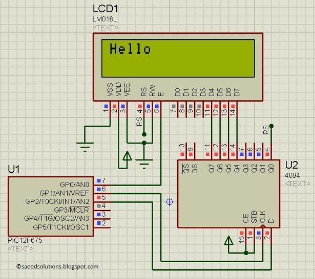
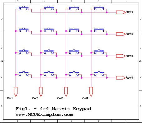
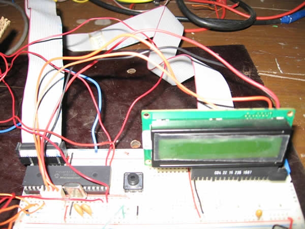
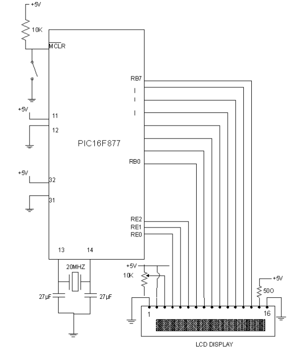
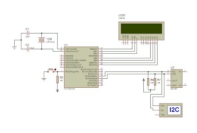
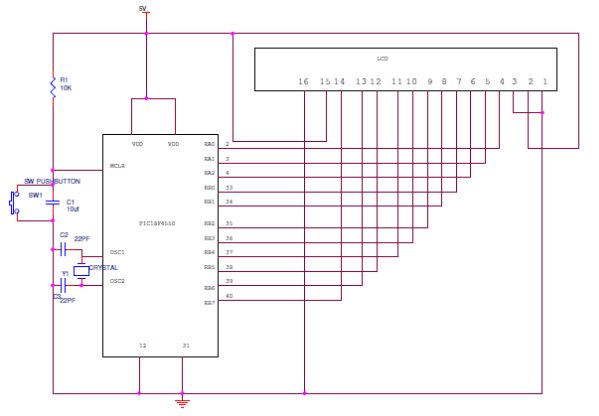
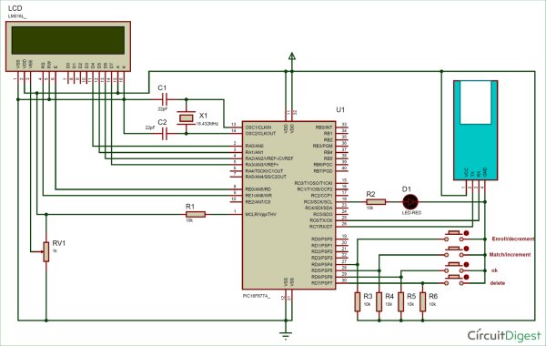
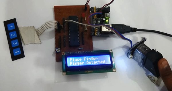
So, first of all, we need to make the all the required connection as shown in Circuit Diagram below. Connections are simple, we have just connected fingerprint module to PIC microcontroller’s UART. A 16×2 LCD is used for displaying all messages. A 10k pot is also used with LCD for controlling the contrast of the same. 16×2 LCD data pins are connected PORTA pins. LCD’s d4, d5, d6, and d7 pins are connected with Pin RA0, RA1, RA2, and RA3 of PIC microcontroller respectively. Four push buttons (or keypad) is connected to PORTD’s Pin RD0, RD1, RD2, and RD. LED is also connected at port PORTC’s pin RC3. Here we have used an 18.432000 MHz external crystal oscillator to clock the microcontroller.

Circuit-Diagram-for-Interfacing-Fingerprint-Sensor-using-PIC-Microcontroller

Operation of Fingerprint Sensor with PIC Microcontroller

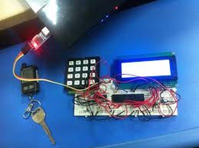
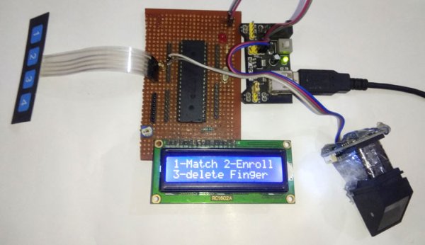
Operation of this project is simple, just upload hex file, generated from source code, into the PIC microcontroller with the help of PIC programmer or burner (PIckit2 or Pickit3 or others)and then you will see some intro messages over LCD and then the user will be asked to enter a choice for operations. To match fingerprint user need to press key 1 then LCD will ask for Place Finger on Finger Print Sensor. Now by putting a finger over fingerprint module, we can check whether our fingerprints are already stored or not. If your fingerprint is stored then LCD will show the message with the storing ID of fingerprint-like ID:2’ otherwise it will show ‘Not Found’.

Now to enroll a finger Print, the user needs to press enroll button or key 2 and follow the instructions messages on the LCD screen.

If the user wants to delete any of fingerprints then the user needs to press the delete button or key 3. After which, LCD will ask for the ID of the fingerprint which is to be deleted. Now by using increment push button or key 1(match push button or key 1) and decrement push button or key 2 (enroll push button or key 2) for increment and decrement, the user can select the ID of saved Finger Print and press OK button to delete that fingerprint. For more understanding have a look at the video given at the end of the project.

Fingerprint-Sensor-using-PIC-Microcontroller-in-action

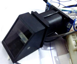
FingerPrint interfacing Note: Program of this project is a little bit complex for a beginner. But its simple interfacing code made by using reading r305 fingerprint module datasheet. All the instruction of functioning of this fingerprint module is given in the datasheet.

Here we have used a frame format to talk with fingerprint module. Whenever we send a command or data request frame to fingerprint module it responds us with the same frame format containing data or information related to applied command. All of the data and command frame format has been given in the user manual or in the datasheet of R305 fingerprint module.

Programming Explanation

In programming, we have used the below frame format.

Programming Explanation using Pic-Microcontroller

We begin the program by setting the configuration bits and defining macros and pins for LCD, Buttons and LED, which you can check in the complete code given at the end of this project. If you are new to PIC Microcontroller then start with Getting started with PIC Microcontroller Project.

Then we declared and initialized some variable and array, and made a frame that we need to use in this project to interface fingerprint module with PIC microcontroller.

uchar buf[20];
uchar buf1[20];
volatile uint index=0;
volatile int flag=0;
uint msCount=0;
uint g_timerflag=1;
volatile uint count=0;
uchar data[10];
uint id=1;

enum
{
 CMD,
 DATA,
 SBIT_CREN=4,
 SBIT_TXEN,
 SBIT_SPEN,
};

const char passPack[]={0xEF, 0x1, 0xFF, 0xFF, 0xFF, 0xFF, 0x1, 0x0, 0x7, 0x13, 0x0, 0x0, 0x0, 0x0, 0x0, 0x1B};
const char f_detect[]={0xEF, 0x1, 0xFF, 0xFF, 0xFF, 0xFF, 0x1, 0x0, 0x3, 0x1, 0x0, 0x5};
const char f_imz2ch1[]={0xEF, 0x1, 0xFF, 0xFF, 0xFF, 0xFF, 0x1, 0x0, 0x4, 0x2, 0x1, 0x0, 0x8};
const char f_imz2ch2[]={0xEF, 0x1, 0xFF, 0xFF, 0xFF, 0xFF, 0x1, 0x0, 0x4, 0x2, 0x2, 0x0, 0x9};
const char f_createModel[]={0xEF,0x1,0xFF,0xFF,0xFF,0xFF,0x1,0x0,0x3,0x5,0x0,0x9};
char f_storeModel[]={0xEF,0x1,0xFF,0xFF,0xFF,0xFF,0x1,0x0,0x6,0x6,0x1,0x0,0x1,0x0,0xE};
const char f_search[]={0xEF, 0x1, 0xFF, 0xFF, 0xFF, 0xFF, 0x1, 0x0, 0x8, 0x1B, 0x1, 0x0, 0x0, 0x0, 0xA3, 0x0, 0xC8};
char f_delete[]={0xEF,0x1,0xFF,0xFF,0xFF,0xFF,0x1,0x0,0x7,0xC,0x0,0x0,0x0,0x1,0x0,0x15};

After it, we have made LCD function to drive LCD.

void lcdwrite(uchar ch,uchar rw)
{
     LCDPORT= ch>>4 & 0x0F;
     RS=rw;
     EN=1;
     __delay_ms(5);
     EN=0;
     LCDPORT= ch & 0x0F;
     EN=1;
     __delay_ms(5);
     EN=0;   
}

​lcdprint(char *str)
{

    while(*str)
    {
        lcdwrite(*str++,DATA);
        //__delay_ms(20);
    }
}

lcdbegin()
{
    uchar lcdcmd[5]={0x02,0x28,0x0E,0x06,0x01};
    uint i=0;
    for(i=0;i<5;i++)
    lcdwrite(lcdcmd[i], CMD);
}

Given function is used for initializing UART

void serialbegin(uint baudrate)
{
  SPBRG = (18432000UL/(long)(64UL*baudrate))-1;      // baud rate @18.432000Mhz Clock
    TXSTAbits.SYNC = 0;                              //Setting Asynchronous Mode, ie UART
    RCSTAbits.SPEN = 1;                              //Enables Serial Port
    TRISC7 = 1;                                   //As Prescribed in Datasheet
    TRISC6 = 0;                                   //As Prescribed in Datasheet
    RCSTAbits.CREN = 1;                                     //Enables Continuous Reception
    TXSTAbits.TXEN = 1;                                     //Enables Transmission

    GIE  = 1; // ENABLE interrupts
    INTCONbits.PEIE = 1; // ENable peripheral interrupts.
    PIE1bits.RCIE   = 1; // ENABLE USART receive interrupt
    PIE1bits.TXIE   = 0; // disable USART TX interrupt

    PIR1bits.RCIF = 0;
}

Given functions are used for transferring commands to fingerprint Module and receiving data from fingerprint module.

void serialwrite(char ch)
{
    while(TXIF==0);  // Wait till the transmitter register becomes empty
    TXIF=0;          // Clear transmitter flag
    TXREG=ch;        // load the char to be transmitted into transmit reg
}

serialprint(char *str)
{
    while(*str)
    {
        serialwrite(*str++);
    }
}

void interrupt SerialRxPinInterrupt(void)
{
    if((PIR1bits.RCIF == 1) && (PIE1bits.RCIE == 1))
    {
       
        uchar ch=RCREG;
        buf[index++]=ch;
        if(index>0)
            flag=1;
        RCIF = 0; // clear rx flag
    } 
}

void serialFlush()
{
    for(int i=0;i<sizeof(buf);i++)
    {
        buf[i]=0;
    }
}

After it we need to make a function which prepares data that is to be transmitted to fingerprint and decode the data coming from fingerprint module.

int sendcmd2fp(char *pack, int len)
{
  uint res=ERROR;
  serialFlush();
  index=0;
  __delay_ms(100);
  for(int i=0;i<len;i++)
  {
    serialwrite(*(pack+i));
  }
  __delay_ms(1000);
  if(flag == 1)
  {
    if(buf[0] == 0xEF && buf[1] == 0x01)
    {
        if(buf[6] == 0x07)   // ack
        {
        if(buf[9] == 0)
        {
            uint data_len= buf[7];
            data_len<<=8;
            data_len|=buf[8];
            for(int i=0;i<data_len;i++)
                data[i]=0;
            for(int i=0;i<data_len-2;i++)
            {
                data[i]=buf[10+i];
            }
            res=PASS;
        }

        else
        {
         res=ERROR;
        }
        }
    }

Now, there are four function available in the code for four different task:

  • Function for input the fingerprint ID – unit getId()
  • Function for matching finger – void matchFinger()
  • Function for enrolling new finger – void enrolFinger()
  • Function for deleting a finger – void deleteFinger()

The complete code with all the four function is given at the end.

Now in the main function, we initialize GPIOs, LCD, UART and check whether the fingerprint module is connected with a microcontroller or not. Then it shows some intro messages over LCD. Finally in while loop we read all keys or push buttons to operate the project.

int main()
{           
  void (*FP)(); 
  ADCON1=0b00000110;
  LEDdir= 0;
  SWPORTdir=0xF0;
  SWPORT=0x0F;
  serialbegin(57600);
  LCDPORTDIR=0x00;
  TRISE=0;
  lcdbegin();
  lcdprint("Fingerprint");
  lcdwrite(192,CMD);
  lcdprint("Interfacing");
  __delay_ms(2000);
  lcdwrite(1,CMD);
  lcdprint("Using PIC16F877A");
  lcdwrite(192,CMD);
  lcdprint("Circuit Digest");
  __delay_ms(2000);
  index=0;   
  while(sendcmd2fp(&passPack[0],sizeof(passPack)))
  {
     lcdwrite(1,CMD);
     lcdprint("FP Not Found");
     __delay_ms(2000);
     index=0;
  }
  lcdwrite(1,CMD);
  lcdprint("FP Found");
  __delay_ms(1000);
  lcdinst();
  while(1)
  {
    FP=match<enrol?matchFinger:enrol<delet?enrolFinger:delet<enrol?deleteFinger:lcdinst;
    FP();
  }
  return 0;
}
Code

#define _XTAL_FREQ 18432000

#include <xc.h>
#include<pic.h>
#include <stdio.h>
#include <stdlib.h>

// BEGIN CONFIG
#pragma config FOSC = HS // Oscillator Selection bits (HS oscillator)
#pragma config WDTE = OFF // Watchdog Timer Enable bit (WDT enabled)
#pragma config PWRTE = OFF // Power-up Timer Enable bit (PWRT disabled)
#pragma config BOREN = ON // Brown-out Reset Enable bit (BOR enabled)
#pragma config LVP = OFF // Low-Voltage (Single-Supply) In-Circuit Serial Programming Enable bit (RB3 is digital I/O, HV on MCLR must be used for programming)
#pragma config CPD = OFF // Data EEPROM Memory Code Protection bit (Data EEPROM code protection off)
#pragma config WRT = OFF // Flash Program Memory Write Enable bits (Write protection off; all program memory may be written to by EECON control)
#pragma config CP = OFF // Flash Program Memory Code Protection bit (Code protection off)
//END CONFIG

#define uchar unsigned char
#define uint unsigned int

#define LCDPORTDIR TRISA
#define LCDPORT PORTA
#define RS RE1
#define EN RE0

#define SWPORTdir TRISD
#define SWPORT PORTD
#define enrol RD4
#define match RD5
#define delet RD7

#define ok RD6
#define up RD5
#define down RD4

#define LEDdir TRISC3
#define LED RC3

#define HIGH 1
#define LOW 0

#define PASS 0
#define ERROR 1

#define checkKey(id) id=up<down?++id:down<up?–id:id;

uchar buf[20];
uchar buf1[20];
volatile uint index=0;
volatile int flag=0;
uint msCount=0;
uint g_timerflag=1;
volatile uint count=0;
uchar data[10];
uint id=1;

enum
{
CMD,
DATA,
SBIT_CREN=4,
SBIT_TXEN,
SBIT_SPEN,
};


const char passPack[]={0xEF, 0x1, 0xFF, 0xFF, 0xFF, 0xFF, 0x1, 0x0, 0x7, 0x13, 0x0, 0x0, 0x0, 0x0, 0x0, 0x1B};
const char f_detect[]={0xEF, 0x1, 0xFF, 0xFF, 0xFF, 0xFF, 0x1, 0x0, 0x3, 0x1, 0x0, 0x5};
const char f_imz2ch1[]={0xEF, 0x1, 0xFF, 0xFF, 0xFF, 0xFF, 0x1, 0x0, 0x4, 0x2, 0x1, 0x0, 0x8};
const char f_imz2ch2[]={0xEF, 0x1, 0xFF, 0xFF, 0xFF, 0xFF, 0x1, 0x0, 0x4, 0x2, 0x2, 0x0, 0x9};
const char f_createModel[]={0xEF,0x1,0xFF,0xFF,0xFF,0xFF,0x1,0x0,0x3,0x5,0x0,0x9};
char f_storeModel[]={0xEF,0x1,0xFF,0xFF,0xFF,0xFF,0x1,0x0,0x6,0x6,0x1,0x0,0x1,0x0,0xE};
const char f_search[]={0xEF, 0x1, 0xFF, 0xFF, 0xFF, 0xFF, 0x1, 0x0, 0x8, 0x1B, 0x1, 0x0, 0x0, 0x0, 0xA3, 0x0, 0xC8};
char f_delete[]={0xEF,0x1,0xFF,0xFF,0xFF,0xFF,0x1,0x0,0x7,0xC,0x0,0x0,0x0,0x1,0x0,0x15};


void lcdwrite(uchar ch,uchar rw)
{
LCDPORT= ch>>4 & 0x0F;
RS=rw;
EN=1;
__delay_ms(5);
EN=0;
LCDPORT= ch & 0x0F;
EN=1;
__delay_ms(5);
EN=0;
}

lcdprint(char *str)
{
while(*str)
{
lcdwrite(*str++,DATA);
//__delay_ms(20);
}
}

lcdbegin()
{
uchar lcdcmd[5]={0x02,0x28,0x0E,0x06,0x01};
uint i=0;
for(i=0;i<5;i++)
lcdwrite(lcdcmd[i], CMD);
}

void lcdinst()
{
lcdwrite(0x80, CMD);
lcdprint(“1-Match 2-Enroll”);
lcdwrite(0xc0, CMD);
lcdprint(“3-delete Finger”);
__delay_ms(10);
}

void serialbegin(uint baudrate)
{
SPBRG = (18432000UL/(long)(64UL*baudrate))-1;      // baud rate @18.432000Mhz Clock
TXSTAbits.SYNC = 0;                              //Setting Asynchronous Mode, ie UART
RCSTAbits.SPEN = 1;                              //Enables Serial Port
TRISC7 = 1;                                   //As Prescribed in Datasheet
TRISC6 = 0;                                   //As Prescribed in Datasheet
RCSTAbits.CREN = 1;                                     //Enables Continuous Reception
TXSTAbits.TXEN = 1;                                     //Enables Transmission

GIE  = 1; // ENABLE interrupts
INTCONbits.PEIE = 1; // ENable peripheral interrupts.
PIE1bits.RCIE   = 1; // ENABLE USART receive interrupt
PIE1bits.TXIE   = 0; // disable USART TX interrupt

PIR1bits.RCIF = 0;

}

void serialwrite(char ch)
{
while(TXIF==0);  // Wait till the transmitter register becomes empty
TXIF=0;          // Clear transmitter flag
TXREG=ch;        // load the char to be transmitted into transmit reg
}

serialprint(char *str)
{
while(*str)
{
serialwrite(*str++);
}
}

void interrupt SerialRxPinInterrupt(void)
{
if((PIR1bits.RCIF == 1) && (PIE1bits.RCIE == 1))
{

uchar ch=RCREG;
buf[index++]=ch;
if(index>0)
flag=1;
RCIF = 0; // clear rx flag
}
}

void serialFlush()
{
for(int i=0;i<sizeof(buf);i++)
{
buf[i]=0;
}
}

int sendcmd2fp(char *pack, int len)
{
uint res=ERROR;
serialFlush();
index=0;
__delay_ms(100);
for(int i=0;i<len;i++)
{
serialwrite(*(pack+i));
}
__delay_ms(1000);
if(flag == 1)
{
if(buf[0] == 0xEF && buf[1] == 0x01)
{
if(buf[6] == 0x07)   // ack
{
if(buf[9] == 0)
{
uint data_len= buf[7];
data_len<<=8;
data_len|=buf[8];
for(int i=0;i<data_len;i++)
data[i]=0;
for(int i=0;i<data_len-2;i++)
{
data[i]=buf[10+i];
}
res=PASS;
}

else
{
res=ERROR;
}
}
}
index=0;
flag=0;
return res;
}
}

uint getId()
{
uint id=0;
lcdwrite(1, CMD);
while(1)
{
lcdwrite(0x80, CMD);
checkKey(id);
sprintf(buf1,”Enter Id:%d  “,id);
lcdprint(buf1);
__delay_ms(200);
if(ok == LOW)
return id;
}
}

void matchFinger()
{
lcdwrite(1,CMD);
lcdprint(“Place Finger”);
lcdwrite(192,CMD);
__delay_ms(2000);
if(!sendcmd2fp(&f_detect[0],sizeof(f_detect)))
{
if(!sendcmd2fp(&f_imz2ch1[0],sizeof(f_imz2ch1)))
{
if(!sendcmd2fp(&f_search[0],sizeof(f_search)))
{
lcdwrite(1,CMD);
lcdprint(“Finger Found”);
uint id= data[0];
id<<=8;
id+=data[1];
uint score=data[2];
score<<=8;
score+=data[3];
sprintf(buf1,”Id:%d  Score:%d”,id,score);
lcdwrite(192,CMD);
lcdprint(buf1);
LED=1;
__delay_ms(1000);
LED=0;
}

else
{
lcdwrite(1,CMD);
lcdprint(“Not Found”);
}
}
}

else
{
lcdprint(“No Finger”);
}
__delay_ms(2000);
}

void enrolFinger()
{
lcdwrite(1,CMD);
lcdprint(“Enroll Finger”);
__delay_ms(2000);
lcdwrite(1,CMD);
lcdprint(“Place Finger”);
lcdwrite(192,CMD);
__delay_ms(1000);
if(!sendcmd2fp(&f_detect[0],sizeof(f_detect)))
{
if(!sendcmd2fp(&f_imz2ch1[0],sizeof(f_imz2ch1)))
{
lcdprint(“Finger Detected”);
__delay_ms(1000);
lcdwrite(1,CMD);
lcdprint(“Place Finger”);
lcdwrite(192,CMD);
lcdprint(”    Again   “);
__delay_ms(2000);
if(!sendcmd2fp(&f_detect[0],sizeof(f_detect)))
{
if(!sendcmd2fp(&f_imz2ch2[0],sizeof(f_imz2ch2)))
{
lcdwrite(1,CMD);
lcdprint(“Finger Detected”);
__delay_ms(1000);
if(!sendcmd2fp(&f_createModel[0],sizeof(f_createModel)))
{
id=getId();
f_storeModel[11]= (id>>8) & 0xff;
f_storeModel[12]= id & 0xff;
f_storeModel[14]= 14+id;
if(!sendcmd2fp(&f_storeModel[0],sizeof(f_storeModel)))
{
lcdwrite(1,CMD);
lcdprint(“Finger Stored”);
sprintf(buf1,”Id:%d”,id);
lcdwrite(192,CMD);
lcdprint(buf1);
__delay_ms(1000);
}

else
{
lcdwrite(1,CMD);
lcdprint(“Finger Not Stored”);
}
}
else
lcdprint(“Error”);
}
else
lcdprint(“Error”);
}
else
lcdprint(“No Finger”);
}
}
else
{
lcdprint(“No Finger”);
}
__delay_ms(2000);
}

void deleteFinger()
{
id=getId();
f_delete[10]=id>>8 & 0xff;
f_delete[11]=id & 0xff;
f_delete[14]=(21+id)>>8 & 0xff;
f_delete[15]=(21+id) & 0xff;
if(!sendcmd2fp(&f_delete[0],sizeof(f_delete)))
{
lcdwrite(1,CMD);
sprintf(buf1,”Finger ID %d “,id);
lcdprint(buf1);
lcdwrite(192, CMD);
lcdprint(“Deleted Success”);

}
else
{
lcdwrite(1,CMD);
lcdprint(“Error”);
}
__delay_ms(2000);
}
int main()
{
void (*FP)();
ADCON1=0b00000110;
LEDdir= 0;
SWPORTdir=0xF0;
SWPORT=0x0F;
serialbegin(57600);
LCDPORTDIR=0x00;
TRISE=0;
lcdbegin();
lcdprint(“Fingerprint”);
lcdwrite(192,CMD);
lcdprint(“Interfacing”);
__delay_ms(2000);
lcdwrite(1,CMD);
lcdprint(“Using PIC16F877A”);
lcdwrite(192,CMD);
lcdprint(“Circuit Digest”);
__delay_ms(2000);
index=0;
while(sendcmd2fp(&passPack[0],sizeof(passPack)))
{
lcdwrite(1,CMD);
lcdprint(“FP Not Found”);
__delay_ms(2000);
index=0;
}
lcdwrite(1,CMD);
lcdprint(“FP Found”);
__delay_ms(1000);
lcdinst();
while(1)
{
FP=match<enrol?matchFinger:enrol<delet?enrolFinger:delet<enrol?deleteFinger:lcdinst;
FP();
}
return 0;
}

The post Interfacing Fingerprint Sensor with PIC Microcontroller appeared first on PIC Microcontroller.

Thermal Printer interfacing with PIC16F877A

$
0
0

Thermal printer is often referred as receipt printer. It is widely used in restaurants, ATM, shops and many other places where receipts or bill is required. It is a cost-effective solution and very handy to use from the user’s side as well as from the developer’s side. A thermal printer uses a special printing process which uses thermochromic paper or thermal paper for printing. The printer head is heated at a certain temperature that when the thermal paper passes from the print head, the paper coating turns black in the areas where the printer head is heated.

In this tutorial, we will interface a thermal printer CSN A1 with widely used PIC microcontroller PIC16F877A. Here in this project, a thermal printer is connected across PIC16F877A and a tactile switch is used to start the printing. A notification LED is also used to notify the printing status. It will glow only when the printing activity is going on.

Thermal Printer interfacing with PIC16F877A

Printer Specification and Connections

We are using CSN A1 Thermal Printer from Cashino, which is available easily and the price is not too high.

CSN A1 Thermal Printer from Cashino

If we see the specification on its official website, we will see a table which provides the detailed specifications-

CSN-A1 Thermal Printer Specification

On the back side of the printer, we will see the following connection-

back side of the printer

The TTL connector provides the Rx Tx connection to communicate with the microcontroller unit. We can also use the RS232 protocol to communicate with the printer. The power connector is for powering the printer and the button is used for printer testing purpose. When the printer is being powered, if we push the self-test button the printer, will print a sheet where specifications and sample lines will be printed. Here is the self-test sheet-

 self-test sheet

As we can see the printer use 9600 baud rate to communicate with the microcontroller unit. The printer can print ASCII characters.  The communication is very easy, we can print anything by simply using UART, transmitting string or character.

The printer needs a 5V 2A power supply for heating the printer head. This is the drawback of the thermal printer as it takes huge load current during the printing process.

Prerequisites

To make the following project, we need the following things:-

  1. Breadboard
  2. Hook up wires
  3. PIC16F877A
  4. 2pcs 33pF ceramic disc capacitor
  5. 680R resistor
  6. Any color led
  7. Tactile switch
  8. 2pcs 4.7k resistors
  9. Thermal Printer CSN A1 with paper roll
  10. 5V 2A rated power supply unit.

Circuit Diagram and Explanation

Schematic for controlling printer with PIC Microcontroller is given below:

Circuit Diagram

Here we are using PIC16F877A as microcontroller unit. A 4.7k resistor is used to connect MCLR pin to the 5V power supply. We have also connected an external oscillator of 20 MHz with 33pF capacitors for the clock signal. A notification LED is connected across RB2 port with 680R led current limiting resistor. The Tactile switch is connected across RB0 pin when the button is pressed it will provide Logic High otherwise the pin will receive Logic low by the 4.7k resistor.

The printer CSN A1 is connected using the cross configuration, Microcontroller Transmit pin is connected with the printer’s Receive pin. The printer also connected with the 5V and GND supply.

We constructed the circuit in a breadboard and tested it.

circuit in a breadboard and tested it (1)
circuit in a breadboard and tested it (2)

Code Explanation

The code is pretty simple to understand. Complete code for interfacing Thermal Printer with PIC16F877A is given at the end of article. As always, we first need to set the configuration bits in the PIC microcontroller.

// PIC16F877A Configuration Bit Settings
// 'C' source line config statements

// CONFIG
#pragma config FOSC = HS        // Oscillator Selection bits (HS oscillator)
#pragma config WDTE = OFF       // Watchdog Timer Enable bit (WDT disabled)
#pragma config PWRTE = OFF      // Power-up Timer Enable bit (PWRT disabled)
#pragma config BOREN = ON       // Brown-out Reset Enable bit (BOR enabled)
#pragma config LVP = OFF         // Low-Voltage (Single-Supply) In-Circuit Serial Programming Enable bit (RB3/PGM pin has PGM function; low-voltage programming enabled)
#pragma config CPD = OFF        // Data EEPROM Memory Code Protection bit (Data EEPROM code protection off)
#pragma config WRT = OFF        // Flash Program Memory Write Enable bits (Write protection off; all program memory may be written to by EECON control)
#pragma config CP = OFF         // Flash Program Memory Code Protection bit (Code protection off)

After that, we defined system hardware related macros and used eusart1.h header file for eusart related hardware control. The UART is configured at 9600 Baud rate inside the header file.

#include <xc.h>
#include "supporting_cfile\eusart1.h"
/*
 * System hardware related macros
 */
#define _XTAL_FREQ 200000000 //Crystal Frequency, used in delay routine
#define printer_sw PORTBbits.RB0 //this macro is for defining the printing switch
#define notification_led PORTBbits.RB2
void system_init(void);

In the main function, we first checked the ‘button press’ and also used switch debounce tactics to eliminate the switch glitches. We have created a if statement for ‘button pressed’ condition. First the led will glow and the UART will print the strings. Custom lines can be generated inside the if statement and can be printed as a string.

void main(void) {    
    system_init();        
    while(1){
        if(printer_sw == 1){ //switch is pressed
            __delay_ms(50); // debounce delay
            if (printer_sw == 1){ // switch is still pressed
                notification_led = 1;                
                put_string("Hello! \n\r");//Print to Thermal printer
                __delay_ms(50);
                put_string("Thermal Printer Tutorial.\n\r");
                __delay_ms(50);
                put_string("Circuit Digest. \n\r");
                __delay_ms(50);
                put_string ("\n\r");
                put_string ("\n\r");
                put_string ("\n\r");
                put_string ("---------------------------- \n \r");
                put_string ("Thank You");
                put_string ("\n\r");
                put_string ("\n\r");
                put_string ("\n\r");
                notification_led = 0;
                } 
            }  
        }
    }

Complete Code and working Video is given below.

Code

/*
* File:   main.c
* Project: Thermal Printer CSN-A1 Interfacing with pic16F877A
* Author: Sourav Gupta.
* Created on 08 September 2018, 16:15
*/

// PIC16F877A Configuration Bit Settings

// ‘C’ source line config statements

// CONFIG
#pragma config FOSC = HS        // Oscillator Selection bits (HS oscillator)
#pragma config WDTE = OFF       // Watchdog Timer Enable bit (WDT disabled)
#pragma config PWRTE = OFF      // Power-up Timer Enable bit (PWRT disabled)
#pragma config BOREN = ON       // Brown-out Reset Enable bit (BOR enabled)
#pragma config LVP = OFF         // Low-Voltage (Single-Supply) In-Circuit Serial Programming Enable bit (RB3/PGM pin has PGM function; low-voltage programming enabled)
#pragma config CPD = OFF        // Data EEPROM Memory Code Protection bit (Data EEPROM code protection off)
#pragma config WRT = OFF        // Flash Program Memory Write Enable bits (Write protection off; all program memory may be written to by EECON control)
#pragma config CP = OFF         // Flash Program Memory Code Protection bit (Code protection off)

#include <xc.h>
#include “supporting_cfile\eusart1.h”
/*
* System hardware related macros
*/
#define _XTAL_FREQ 200000000 //Crystal Frequency, used in delay routine
#define printer_sw PORTBbits.RB0 //this macro is for defining the printing switch
#define notification_led PORTBbits.RB2
void system_init(void);

void main(void) {
system_init();
while(1){
if(printer_sw == 1){ //switch is pressed
__delay_ms(50); // debounce delay
if (printer_sw == 1){ // switch is still pressed
notification_led = 1;
put_string(“Hello! \n\r”);//Print to Thermal printer
__delay_ms(50);
put_string(“Thermal Printer Tutorial.\n\r”);
__delay_ms(50);
put_string(“Circuit Digest. \n\r”);
__delay_ms(50);
put_string (“\n\r”);
put_string (“—————————- \n \r”);
put_string (“Thank You”);
put_string (“\n\r”);
notification_led = 0;
}
}
}
}

void system_init(void){
TRISBbits.TRISB0 = 1; // Setting Printing Switch as input
TRISBbits.TRISB2 = 0;
notification_led = 0;
EUSART1_Initialize(); // This will initialise the Eusart
}

The post Thermal Printer interfacing with PIC16F877A appeared first on PIC Microcontroller.

RFID Interfacing with PIC Microcontroller

$
0
0

RFID stands for Radio Frequency Identification. RFID module can read or write small amount of data into a Passive RFID tag, which can be used in identification process in various systems like Attendance system, security system, voting system etc. RFID is very convenient and easy technology.

RFID-Interfacing-using-PIC-Microcontroller

To read the Passive RFID cards and tag, we need a microcontroller with UART hardware. If we select a microcontroller without UART, we need to implement software UART. Here we are using PIC Microcontroller PIC16F877A for interfacing RFID. We will simply read the unique identification no. of RFID tags and display it on 16×2 LCD.

RFID module and its Working

In this project, we chose EM-18 RFID module, which is small-sized, low cost, and power efficient module. EM-18 RFID module use 125 KHz RF frequency to read passive 125 KHz RFID tags. EM-18 module use Oscillator, demodulator and data decoder to read data from a passive card.

RFID Tag

There are three types of RFID tags available, Passive, Active or Battery-assisted passive. Different kind of RFID tags with a different kind of shapes and sizes are available in the market. Few of them use different frequency for communication purpose. We will use 125Khz Passive RFID cards which holds the unique ID data. Here are the RFID card and tags we are using for this project.

RFID Tag

Working of RFID

Working of RFID

The module uses UART communication protocol in 9600 Baud rate. When a Valid frequency tag is brought into the magnetic field of the EM-18 reader, the BC557 transistor gets on and the buzzer will start beeping, it also glows the LED. We are using a module which is easily available in the market and has complete circuitry with a buzzer, led, and an additional RS232 port.
Here is the RFID board module we are using with pin names. This module also has additional power option.

EM18-RFID-Reader-Module

One thing needs to be kept in mind that the output of EM-18 reader uses 5V logic level. We could use another microcontroller which uses a lower logic level, but in such cases, the additional logic level converter is required. In few cases, the UART pin of the 3.3V microcontroller is often 5V tolerant.

The UART output provides 12-bit ASCII data. First 10 bits are RFID tag number, which is the unique ID and last two digits are used for error testing. Those last two digits are the XOR of the tag number. EM-18 module will read the data from 125 KHz Passive RFID tags or cards.

Those tags or IDs have a factory programmed memory array which stores the unique ID number. As those are passive, so no battery is present in the card or tags, they get energized by the magnetic field of the RF Transceiver module. These RFID tags are made using the EM4102 CMOS IC which is clocked by the magnetic field too.

Material Required

To make this project we need following items-

  1. PIC16F877A
  2. 20Mhz Crystal
  3. 2pcs 33pF ceramic disc capacitor
  4. 16×2 Character LCD
  5. A breadboard
  6. 10k preset pot
  7. 4.7k resistor
  8. Single strand wires to connect
  9. A 5V adapter
  10. RF Module EM-18
  11. 5V Buzzer
  12. 100uF & .1uF 12V capacitor
  13. BC557 Transistor
  14. LED
  15. 2.2k and 470R resistor.

We are using the EM-18 module board with buzzer and led preconfigured. So, the components listed from 11 to 15 are not needed.

Circuit Diagram

Circuit Diagram

The schematic is simple; we connected LCD across port RB and connected the EM-18 module across the UART Rx pin.

We have made the connection on breadboard according to schematic.

breadboard according to schematic-with-PIC-Microcontroller

Code Explanation

As always, first we need to set the configuration bits in the pic microcontroller, define some macros, including libraries and crystal frequency. You can check code for all those in the complete code given at the end.

// PIC16F877A Configuration Bit Settings
// 'C' source line config statements
// CONFIG

#pragma config FOSC = HS        // Oscillator Selection bits (HS oscillator)
#pragma config WDTE = OFF       // Watchdog Timer Enable bit (WDT disabled)
#pragma config PWRTE = OFF      // Power-up Timer Enable bit (PWRT disabled)
#pragma config BOREN = ON       // Brown-out Reset Enable bit (BOR enabled)
#pragma config LVP = OFF         // Low-Voltage (Single-Supply) In-Circuit Serial Programming Enable bit (RB3/PGM pin has PGM function; low-voltage programming enabled)
#pragma config CPD = OFF        // Data EEPROM Memory Code Protection bit (Data EEPROM code protection off)
#pragma config WRT = OFF        // Flash Program Memory Write Enable bits (Write protection off; all program memory may be written to by EECON control)
#pragma config CP = OFF         // Flash Program Memory Code Protection bit (Code protection off)

#include "supporing_cfile\lcd.h"
#include "supporing_cfile\eusart1.h"

If we see the main function we called a function to initialize the system. We initialize LCD and UART in this function.

/*
 This Function is for system initializations.
 */

void system_init(void){
    TRISB = 0x00; //PORT B set as output pin
    lcd_init(); // This will initialize the lcd
    EUSART1_Initialize(); // This will initialize the Eusart
}

Now, in the main function, we used a 13 bit array which is RFID Number. We receive each bit of the RFID no. using EUSART1_Read(); function, which is declared inside of the UART library. After receiving 12bits, we print the Array as string in the LCD.

void main(void) {
    unsigned char count;
    unsigned char RF_ID[13];    
    system_init();
    lcd_com(0x80);
    lcd_puts("Circuit Digest");    
    while (1){        
        for (count=0; count<12; count++){
            RF_ID[count] = 0;
            RF_ID[count]=EUSART1_Read();
        }        
        lcd_com(0xC0); // Set the cursor for second line beginning
        lcd_puts("ID: ");
        lcd_puts(RF_ID);        
    }
}

Code

/*
* File:   main.c
* Author: Sourav Gupta
* By:- circuitdigest.com
* Created on August 15, 2018, 2:26 PM
*/

// PIC16F877A Configuration Bit Settings

// ‘C’ source line config statements

// CONFIG
#pragma config FOSC = HS        // Oscillator Selection bits (HS oscillator)
#pragma config WDTE = OFF       // Watchdog Timer Enable bit (WDT disabled)
#pragma config PWRTE = OFF      // Power-up Timer Enable bit (PWRT disabled)
#pragma config BOREN = ON       // Brown-out Reset Enable bit (BOR enabled)
#pragma config LVP = OFF         // Low-Voltage (Single-Supply) In-Circuit Serial Programming Enable bit (RB3/PGM pin has PGM function; low-voltage programming enabled)
#pragma config CPD = OFF        // Data EEPROM Memory Code Protection bit (Data EEPROM code protection off)
#pragma config WRT = OFF        // Flash Program Memory Write Enable bits (Write protection off; all program memory may be written to by EECON control)
#pragma config CP = OFF         // Flash Program Memory Code Protection bit (Code protection off)


#include <xc.h>
#include <stdio.h>
#include <string.h>
#include “supporing_cfile\lcd.h”
#include “supporing_cfile\eusart1.h”

/*
Hardware related definition
*/
#define _XTAL_FREQ 200000000 //Crystal Frequency, used in delay

/*
Other Specific definition
*/
void system_init(void); // This will initialize the system.

void main(void) {
unsigned char count;
unsigned char RF_ID[13];
system_init();
lcd_com(0x80);
lcd_puts(“Circuit Digest”);
while (1){
for (count=0; count<12; count++){
RF_ID[count] = 0;
RF_ID[count]=EUSART1_Read();
}
lcd_com(0xC0); // Set the cursor for second line begining
lcd_puts(“ID: “);
lcd_puts(RF_ID);
}
}

/*
This Function is for system initializations.
*/

void system_init(void){
TRISB = 0x00; //PORT B set as output pin
lcd_init(); // This will initialize the lcd
EUSART1_Initialize(); // This will initialize the Eusart
}

The post RFID Interfacing with PIC Microcontroller appeared first on PIC Microcontroller.

Viewing all 111 articles
Browse latest View live


<script src="https://jsc.adskeeper.com/r/s/rssing.com.1596347.js" async> </script>