Quantcast
Channel: interfacing | Battery Guide
Viewing all 111 articles
Browse latest View live

Relay Interfacing with PIC Microcontroller

$
0
0

In this project we will interface a Relay with PIC Microcontroller PIC16F877A. Relay is a mechanical device to control high voltage, high current appliances ‘ON’ or ‘OFF’ from lower voltage levels. Relay provides isolation between two voltage levels and it is generally use to control AC appliances. From mechanical to Solid state relays, there are various type of relays are available in electronics. In this project we will use mechanical relay.

Relay-Interfacing-using-PIC-Microcontroller

In this project we will do the following things-

  1. We will Interface a switch for input from user.
  2. Control an 220V AC bulb with 5V relay.
  3. To control the relay we will use BC547 NPN transistor and the transistor will be controlled from the PIC16F877A. A led will notify the relay ON or OFF condition.

Component Required:

  1. PIC16F877A
  2. 20Mhz Crystal
  3. 2 pcs 33pF ceramic
  4. 3 pcs 4.7k resistors
  5. 1k resistor
  6. 1 LED
  7. BC547 Transistor
  8. 1N4007 Diode
  9. 5V cubic relay
  10. AC bulb
  11. Breadboard
  12. Wires for connecting the parts.
  13. 5V Adapter or any 5V power source with at least 200mA current capabilities.

Relay and its Working:

Relay works same as typical switch. Mechanical relays use temporary magnet made from electromagnetic coil. When we provide enough current across this coil, it became energized and pulls an arm. Due to that the circuit connected across the relay can be closed or open. The Input and Output don’t have any electrical connections and thus it isolates input and output. Learn more about relay and its constructions here.

Relays can be found in different voltage ranges like 5V, 6V, 12V, 18V etc. In this project we will use 5V relay as our working voltage is 5 Volts here. This 5V cubic relay is capable to switch 7A load at 240VAC or 10A load at 110VAC. However instead that huge load, we will use a 220VAC bulb and switch it using the relay.

This is the 5V Relay we are using in this project. The current rating is clearly specified for two voltage levels, 10A at 120VAC and 7A at 240VAC. We need to connect load across the relay less than the specified rating.

5V Cubic Relay using Pic-microcontroller

This relay has 5 pins. If we see the pinout we can see-

KT-603-5V-relay-pinout using Pic microcontroller

The L1 and L2 is the internal electromagnetic coil’s pin. We need to control these two pins for turning the relay ‘ON’ or ‘OFF’. Next three pins are POLE, NO and NC. The pole is connected with the internal metal plate which changes its connection when the relay turns on. In normal condition, POLE is shorted with NCNC stands for normally connected. When the relay turns on, the pole changes its position and become connected with the NONO stands for NormallyOpen.

In our circuit, we have made the relay connection with transistor and diode. Relay with transistor and diode is available in market as Relay Module, so when you use Relay Module you don’t need to connect its driver circuit (Transistor and diode).

KT-603-5V-relay-module using Pic-microcontroller

Relay is used in all the Home Automation Projects to control the AC Home Appliances.
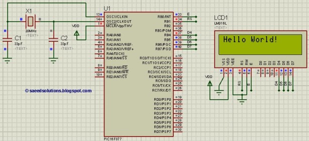
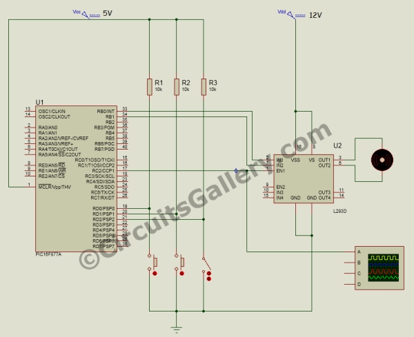
Circuit Diagram:

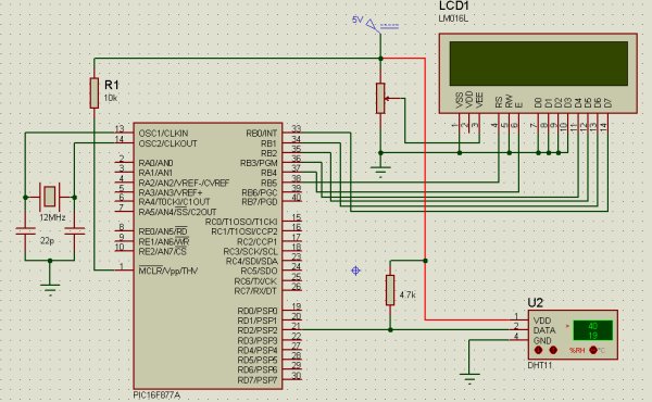
Complete circuit for connecting Relay with PIC Microcontroller is given below:

Circuit Diagram using Pic-microcontroller

In the above schematic pic16F877A is used, where on the port B the LED and Transistor is connected, which is further controlled using the TAC switch at RBO. The R1 provide bias current to the transistor. R2 is a pull-down resistor, used across tactile switch. It will provide logic 0 when the switch is not pressed. The 1N4007 is a clamp diode, used for the relay’s electromagnetic coil. When the relay will turned off, there are chances for high voltage spikes and the diode will suppress it. The transistor is required for driving the relay as it requires more than 50mA of current, that the microcontroller is unable to provide. We can also use ULN2003 instead the transistor, it is a wiser choice if more than two or three relays are required for the application, check the Relay module circuit. The LEDacross port RB2 will notify “relay is on”.

The final circuit will look like this-

final circuit will look like this using Pic microcontroller

Code Explanation:

At the beginning of the main.c file, we added the configuration lines for pic16F877A and also defined the pin names across PORTB.

As always first, we need to set the configuration bits in the pic microcontroller, define some macros, including libraries and crystal frequency. You can check code for all those in the complete code given at the end. We made RB0 as input. In this pin the switch is connected.

#include <xc.h>
/*
 Hardware related definition
 */
#define _XTAL_FREQ 200000000 //Crystal Frequency, used in delay
#define SW PORTBbits.RB0
#define RELAY PORTBbits.RB1
#define LED PORTBbits.RB2

After that, we called system_init() function where we initialized pin direction, and also configured the default state of the pins.

In the system_init() function we will see

void system_init(void){
    TRISBbits.TRISB0 = 1; // Setting Sw as input
    TRISBbits.TRISB1 = 0; // setting LED as output
    TRISBbits.TRISB2 = 0; // setting relay pin as output
    LED = 0;
    RELAY = 0;
    }

In the main function we constantly check the switch press, if we detect the switch press by sensing logic high across RB0; we wait for some time and see whether the switch is still pressed or not, if the switch is still pressed then we will invert the RELAY and LED pin’s state.

void main(void) {
    system_init(); // System getting ready    
    while(1){
        if(SW == 1){ //switch is pressed
            __delay_ms(50); // debounce delay
            if (SW == 1){ // switch is still pressed
                LED = !LED; // inverting the pin status.
                RELAY = !RELAY;
            }
        }
     }
    return;
    }

Complete code and Demo Video for this Relay interfacing is given below.

Code

/*
* File:   main.c
* Author: Sourav Gupta
* By:- circuitdigest.com
* Created on May 30, 2018, 2:26 PM
*/

// PIC16F877A Configuration Bit Settings

// ‘C’ source line config statements

// CONFIG
#pragma config FOSC = HS        // Oscillator Selection bits (HS oscillator)
#pragma config WDTE = OFF       // Watchdog Timer Enable bit (WDT disabled)
#pragma config PWRTE = OFF      // Power-up Timer Enable bit (PWRT disabled)
#pragma config BOREN = ON       // Brown-out Reset Enable bit (BOR enabled)
#pragma config LVP = OFF         // Low-Voltage (Single-Supply) In-Circuit Serial Programming Enable bit (RB3/PGM pin has PGM function; low-voltage programming enabled)
#pragma config CPD = OFF        // Data EEPROM Memory Code Protection bit (Data EEPROM code protection off)
#pragma config WRT = OFF        // Flash Program Memory Write Enable bits (Write protection off; all program memory may be written to by EECON control)
#pragma config CP = OFF         // Flash Program Memory Code Protection bit (Code protection off)


#include <xc.h>
/*
Hardware related definition
*/
#define _XTAL_FREQ 200000000 //Crystal Frequency, used in delay
#define SW PORTBbits.RB0
#define RELAY PORTBbits.RB1
#define LED PORTBbits.RB2

/*
Other Specific definition
*/
void system_init(void);

void main(void) {
system_init(); // System getting ready
while(1){
if(SW == 1){ //switch is pressed
__delay_ms(50); // debounce delay
if (SW == 1){ // switch is still pressed
LED = !LED; // inverting the pin status.
RELAY = !RELAY;
}
}
}
return;
}

/*
This Function is for system initialisations.
*/

void system_init(void){
TRISBbits.TRISB0 = 1; // Setting Sw as input
TRISBbits.TRISB1 = 0; // setting LED as output
TRISBbits.TRISB2 = 0; // setting relay pin as output
LED = 0;
RELAY = 0;
}

The post Relay Interfacing with PIC Microcontroller appeared first on PIC Microcontroller.


4×4 Matrix Keypad Interfacing with PIC Microcontroller

$
0
0

Keypads are widely used input devices being used in various electronics and embedded projects. They are used to take inputs in the form of numbers and alphabets, and feed the same into system for further processing. In this tutorial we are going to interface a 4×4 matrix keypad with PIC16F877A.

Before going into the detail logic and learn how to use the keypad, we will need to know few things.

4x4 Matrix Keypad Interfacing using PIC Microcontroller

Why we need 4×4 Keypad:

Typically we use single I/O pin of a microcontroller unit to read the digital signal, like a switch input. In few applications where 9, 12, 16 keys are needed for input purposes, if we add each key in a microcontroller port, we will end up using 16 I/O ports. This 16 I/O ports are not only for reading I/O signals, but they can be used as peripheral connections too, like ADC supports, I2C, SPI connections are also supported by those I/O pins. As those pins are connected with the switches/keys, we can’t use them but only as I/O ports. This is makes no sense at all. So, how to reduce pin count? The answer is, using a hex keypad or matrix keypad; we can reduce pin counts, which associate 4×4 matrix keys. It will use 8 pins out of which 4 connected in rows and 4 connected in columns, therefore saving 8 pins of the microcontroller’s.

How 4×4 Matrix Keypad works:

4x4 Matrix Keypad works

In the upper image a matrix keypad module is shown at the left. On the right the internal connection is shown as well as port connection. If we see the port there are 8 pins, first 4 from left to right are X1, X2, X3, and X4 are the rows, and last 4 from left to right are Y1, Y2, Y3, Y4 are four columns. If we make 4 rows or X side as output and make them logic low or 0, and make the 4 columns as input and read the keys we will read the switch press when correspondent Y gets 0.

Same thing will happen in n x n matrix where n is the number. That can be 3×3, 6×6 etc.

Now just think that 1 is pressed. Then the 1 is situated at X1 row and Y1 column. If X1 is 0, then the Y1 will be 0. By the same way we can sense each key in the X1 row, by sensing column Y1, Y2, Y3 and Y4. This thing happens for every switch and we will read the position of the switches in the matrix.

Each green circles is the switch and they both are connected together in the same way.

In this tutorial we will interface the key board with following specifications-

  1. We will use internal pull up
  2. We will add key de-bounce option

But when the switches are not pressed we need to make the Y1, Y2, Y3 and Y4 as high or 1. Otherwise we can’t detect the logic changes when the switch is being pressed. But we couldn’t make it by codes or program due to those pins are used as input, not output. So, we will use an internal operation register in the microcontroller and operate those pins as weak pull up enabled mode. By using this, there will be a logic high enable mode when it is in the default state.

Also, when we press key there are spikes or noise are generated with switch contacts, and due to this multiple switch press happens which is not expected. So, we will first detect the switch press, wait for few milliseconds, again check whether the switch is still pressed or not and if the switch is still pressed we will accept the switch press finally otherwise not. This is called as de-bouncing of the switches.

We will implement this all in our code, and make the connection on breadboard.

Material Required:

  1. Breadboard
  2. Pic-kit 3 and development environment in your PC, i.e MPLABX
  3. Wires and connectors
  4. Character LCD 16×2
  5. 20Mhz Crystal
  6. 2 pcs 33pF ceramic disc cap.
  7. 4.7k resistor
  8. 10k preset (variable resistor)
  9. 4×4 Matrix keypad
  10. A 5 V adapter

Circuit Diagram:

4x4-Matrix-Keypad-Interfacing-Circuit-diagram-using-PIC-Microcontroller


4x4-Matrix-Keypad-Interfacing-with-PIC-Microcontroller


We will connect the crystals and the resistor in the associated pins. Also, we will connect the LCD in 4 bit modeacross PORTD. We connected the hex keypad or matrix keypad across the port RB4.

Programming Explanation:

Complete code for interfacing Matrix Keypad with PIC Microcontroller is given at the end. Code is easy and self-explanatory. Keypad library is only thing to be understood in the code. Here we have used keypad.h and lcd.h Library to interface the keypad and 16×2 LCD. So lets see what is happening inside that.

Inside the keypad.h we will see that we have used xc.h header which is default register library, the crystal frequency is defined for the use for the use of delay used in kepad.c file. We defined the keypad ports at PORTRB register and defined individual pins as row (X) and columns (Y).

We also used two functions one for the keypad initialization which will redirect the port as output and input, and a switch press scan which will return the switch press status when called.

#include <xc.h>

#define _XTAL_FREQ 200000000 //Crystal Frequency, used in delay
#define X_1    RB0
#define X_2    RB1
#define X_3    RB2
#define X_4    RB3
#define Y_1    RB4
#define Y_2    RB5
#define Y_3    RB6
#define Y_4    RB7
#define Keypad_PORT          PORTB
#define Keypad_PORT_Direction     TRISB   

void InitKeypad(void);
char switch_press_scan(void);

In the keypad.c we will see that below function will return the key press when the keypad scanner function not return ‘n’.

char switch_press_scan(void)                       // Get key from user
{
            char key = 'n';              // Assume no key pressed
            while(key=='n')              // Wait untill a key is pressed
            key = keypad_scanner();   // Scan the keys again and again
            return key;                  //when key pressed then return its value
}

Below is the keypad reading function. In each step we will make the row X1, X2, X3, and X4 as 0 and reading the Y1, Y2, Y3 and Y4 status. The delay is used for the debounce effect, when the switch is still pressed we will return the value associated with it. When no switch are pressed we will return ‘n ‘.

char keypad_scanner(void)  
{           
            X_1 = 0; X_2 = 1; X_3 = 1; X_4 = 1;    
            if (Y_1 == 0) { __delay_ms(100); while (Y_1==0); return '1'; }
            if (Y_2 == 0) { __delay_ms(100); while (Y_2==0); return '2'; }
            if (Y_3 == 0) { __delay_ms(100); while (Y_3==0); return '3'; }
            if (Y_4 == 0) { __delay_ms(100); while (Y_4==0); return 'A'; }
            
            X_1 = 1; X_2 = 0; X_3 = 1; X_4 = 1;    
            if (Y_1 == 0) { __delay_ms(100); while (Y_1==0); return '4'; }
            if (Y_2 == 0) { __delay_ms(100); while (Y_2==0); return '5'; }
            if (Y_3 == 0) { __delay_ms(100); while (Y_3==0); return '6'; }
            if (Y_4 == 0) { __delay_ms(100); while (Y_4==0); return 'B'; }
            
            X_1 = 1; X_2 = 1; X_3 = 0; X_4 = 1;    
            if (Y_1 == 0) { __delay_ms(100); while (Y_1==0); return '7'; }
            if (Y_2 == 0) { __delay_ms(100); while (Y_2==0); return '8'; }
            if (Y_3 == 0) { __delay_ms(100); while (Y_3==0); return '9'; }
            if (Y_4 == 0) { __delay_ms(100); while (Y_4==0); return 'C'; }
           
            X_1 = 1; X_2 = 1; X_3 = 1; X_4 = 0;    
            if (Y_1 == 0) { __delay_ms(100); while (Y_1==0); return '*'; }
            if (Y_2 == 0) { __delay_ms(100); while (Y_2==0); return '0'; }
            if (Y_3 == 0) { __delay_ms(100); while (Y_3==0); return '#'; }
            if (Y_4 == 0) { __delay_ms(100); while (Y_4==0); return 'D'; }
            
    return 'n';                   
}

We will also set the weak pull up on the last four bits, and also set the direction of the ports as last 4 input and first 4 as output. The OPTION_REG &= 0x7F; is used to set the weak pull up mode on the last pins.

void InitKeypad(void)
{
            Keypad_PORT                = 0x00;        // Set Keypad port pin values zero
            Keypad_PORT_Direction = 0xF0;      // Last 4 pins input, First 4 pins output        
            OPTION_REG &= 0x7F;
}

In the main PIC program (given below) we first set the configuration bits and included few needed libraries. Then in void system_init functions we initialize the keypad and LCD. And finally in in the main function we have read the keypad by calling the switch_press_scan() function and returning the value to lcd.

Download the complete code with header files from here and check the Demonstration video below.

Code

/*
* File:   main.c
* Author: Sourav Gupta
* By:- circuitdigest.com
* Created on April 13, 2018, 2:26 PM
*/

// PIC16F877A Configuration Bit Settings

// ‘C’ source line config statements

// CONFIG
#pragma config FOSC = HS        // Oscillator Selection bits (HS oscillator)
#pragma config WDTE = OFF       // Watchdog Timer Enable bit (WDT disabled)
#pragma config PWRTE = OFF      // Power-up Timer Enable bit (PWRT disabled)
#pragma config BOREN = ON       // Brown-out Reset Enable bit (BOR enabled)
#pragma config LVP = OFF         // Low-Voltage (Single-Supply) In-Circuit Serial Programming Enable bit (RB3/PGM pin has PGM function; low-voltage programming enabled)
#pragma config CPD = OFF        // Data EEPROM Memory Code Protection bit (Data EEPROM code protection off)
#pragma config WRT = OFF        // Flash Program Memory Write Enable bits (Write protection off; all program memory may be written to by EECON control)
#pragma config CP = OFF         // Flash Program Memory Code Protection bit (Code protection off)


#include <xc.h>
#include <stdio.h>
#include <string.h>
#include “supporing_cfile/lcd.h”
#include “supporing_cfile/Keypad.h”

/*
Hardware related definition
*/
#define _XTAL_FREQ 200000000 //Crystal Frequency, used in delay

/*
Other Specific definition
*/
void system_init(void);

void main(void){
system_init();
char Key = ‘n’;
lcd_com(0x80);
lcd_puts(“CircuitDigest”);
lcd_com(0xC0);
while(1){
Key = switch_press_scan();
lcd_data(Key);
}

}

/*
*  System Init
*/

void system_init(void){
TRISD = 0x00;
lcd_init(); // This will initialise the lcd
InitKeypad();
}

The post 4×4 Matrix Keypad Interfacing with PIC Microcontroller appeared first on PIC Microcontroller.

Interfacing Joystick with PIC Microcontroller

$
0
0

Input devices play a vital role in any electronics projects. These input device help the user to interact with the digital world. An input device can be as simple as a push button or as complicated as a touch screen; it varies based on the requirement of the project. In this tutorial we are going to learn how to interface a joystick with our PIC microcontroller, a joystick is a cool way to interact with the digital world and almost everyone would have used one for playing video games in their adolescence age.

Interfacing-Joystick-with-PIC-Micro-controller

A joystick might seem to be a sophisticated device, but it actually is just a combination of two Potentiometers and a push button. Hence it is also very easy to interface with any MCU provided we know how to use the ADC feature of that MCU. Hence it is would be just a work around for interfacing the Joystick.

Material Required

  • PicKit 3 for programming
  • Joy Stick module
  • PIC16F877A IC
  • 40 – Pin IC holder
  • Perf board
  • 20 MHz Crystal OSC
  • Bergstik pins
  • 220ohm Resistor
  • 5-LEDs of any colour
  • 1 Soldering kit
  • IC 7805
  • 12V Adapter
  • Connecting wires
  • Breadboard

Understanding the Joystick Module:

Joysticks are available in different shapes and sizes. A typical Joystick module is shown in the figure below. A Joystick is nothing more than a couple of potentiometers and push button mounted over a smart mechanical arrangement. The potentiometer is used to keep track of the X and Y movement of the joystick and the button is used to sense if the joystick is pressed. Both the Potentiometers output an analog voltage which depends on the position of the joystick. And we can get the direction of movement by interpreting these voltage changes using some microcontroller.

Understanding the Joystick Module using Pic-microcontroller

Before interfacing any sensor or module with a microcontroller it is important to know how it functions. Here our joystick has 5 output pins out of which two is for power and three is for data. The module should be powered with +5V. The data pins are named as VRX, VRY and SW.

The term “VRX” stands for Variable voltage on X-axis and the term “VRY” stands for Variable voltage in Y-axis and “SW” stands for switch.

So when we move the joystick to left or right the voltage value on VRX will vary and when we vary it up or down VRY will vary. Similarly when we move it diagonally we both VRX and VRY will vary. When we press the switch the SW pin will be connected to ground. The below figure will help you to understand the Output values much better

Axis-value-of-Joystick-Module using Pic-microcontroller

Circuit Diagram:

Now that we know how the Joy stick works, we can arrive at a conclusion that we will need two ADC pins and one digital input pin to read all the three data pins of the Joystick module. The complete circuit diagram is shown in the picture below

Interfacing-circuit-diagram-of-Joystick-with-PIC-Micro-controller

As you can see in circuit diagram, instead of the joystick we have used two potentiometer RV1 and RV3 as analog voltage inputs and a logic input for the switch. You could follow the labels written in violet colour to match the pins names and make your connections accordingly.

Note that the Analog pins are connected to channels A0 and A1 and the digital switch is connected to RB0. We will also have 5 LED lights connected as output, so that we can glow one based on the direction the joystick is moved. So these output pins are connected to PORT C from RC0 to RC4. Once we have panned our circuit diagram we can proceed with the programming, then simulate the program on this circuit then build the circuit on a breadboard and then upload the program to the hardware. To give you an idea my hardware after making the above connections is shown below

Interfacing-circuit-hardware-of-Joystick-using-PIC-Micro-controller

Programming for Interfacing the Joystick:

The program to interface joystick with PIC is simple and straight forward. We already know that which pins the Joystick is connected to and what their function is, so we simply have to read the analog voltage from the pins and control the output LED’s accordingly.

The complete program to do this is given at the end of this document, but for explaining things I am breaking the code in to small meaningful snippets below.

As always the program is started by setting the configuration bits, we are not going to discuss much about setting configurations bits because we have already learnt it in the LED Blinking project and it is the same for this project also. Once the configurations bits are set we have to define the ADC functions for using the ADC module in our PIC. These function were also learnt in the how to use ADC with PIC tutorial. After that, we have to declare which pins are inputs and which are output pins. Here the LED is connected to PORTC so they are output pins and the Switch pin of Joystick is a digital input pin. So we use the following lines to declare the same:

//*****I/O Configuration****//
TRISC=0X00; //PORT C is used as output ports
PORTC=0X00; //MAke all pins low
TRISB0=1; //RB0 is used as input
//***End of I/O configuration**///

The ADC pins need not be defined as input pins because they when using the ADC function it will be assigned as input pin. Once the pins are defined, we can call the ADC_initialize function which we defined earlier. This function will set the required ADC registers and prepare the ADC module.

ADC_Initialize(); //Configure the ADC module

Now, we step into our infinite while loop. Inside this loop we have to monitor the values of VRX, VRY and SW and based on the values we have to control the led’s output.  We can begin the monitoring process by reading the analog voltage of VRX and VRY by using the below lines

    int joy_X = (ADC_Read(0)); //Read the X-Axis of joystick
    int joy_Y = (ADC_Read(1)); //Read the Y-Axis of Joystick

This line will save the value of VRX and VRY in the variable joy_X and joy_Y respectively. The function ADC_Read(0)means we are reading the ADC value from channel 0 which is pin A0. We have connected VRX and VRY to pin A0 and A1 and so we read from 0 and 1.

If you can recollect from our ADC tutorial we know that we read the Analog Voltage the PIC being a digital device will read it from 0 to 1023. This value depends on the position of the joystick module. You can use the label diagram above to know what value you can expect for every position of the joystick.

Here I have used the limit value of 200 as lower limit and a value of 800 as upper limit. You can use anything you want. So let’s use these values and start glowing the LED s accordingly. To do this we have to compare the value of joy_X with the pre-defined values using an IF loop and make the LED pins high or low as shown below. The comment lines will help you to understand better

    if (joy_X < 200) //Joy moved up
    {RC0=0; RC1=1;} //Glow upper LED
    else if (joy_X > 800) //Joy moved down
    {RC0=1; RC1=0;} //Glow Lower LED
    else //If not moved
    {RC0=0; RC1=0;} //Turn off both led

We can similarly do the same for the value of Y-axis as well. We just have to replace the variable joy_X with joy_Y and also control the next two LED pins as shown below. Note that when the joystick is not moved we turn off both the LED lights.

    if (joy_Y < 200) //Joy moved Left
    {RC2=0; RC3=1;} //Glow left LED
    else if (joy_Y > 800) //Joy moved Right
    {RC2=1; RC3=0;} //Glow Right LED
    else //If not moved
    {RC2=0; RC3=0;} //Turn off both LED

Now we have one more final thing to do, we have to check the switch if is pressed. The switch pin is connected to RB0 so we can again use if loop and check if it is on. If it is pressed we will turn of the LED to indicate that the switch has been pressed.

    if (RB0==1) //If Joy is pressed
        RC4=1; //Glow middle LED
    else
        RC4=0; //OFF middle LED

Simulation View:

The complete project can be simulated using the Proteus software. Once you have written the program compile the code and link the hex code of the simulation to the circuit. Then you should notice the LED lights glowing according to the position of the potentiometers. The simulation is shown below:

Simulation-of-Interfacing-Joystick-with-PIC-Micro-controller

Hardware and Working:

After verifying the code using the Simulation, we can build the circuit on a bread board. If you have been following the PIC tutorials you would have noticed that we use the same perf board which has the PIC and 7805 circuit soldered to it.  If you are also interested in making one so that you use it with all your PIC projects then solder the circuit on a perf board.  Or you can also build the complete circuit on a breadboard also. Once the hardware is done it would be something like this below.

Hardware and Working using Pic-microcontroller

Now upload the code to the PIC microcontroller using the PICkit3. You can refer the LED Blink project for guidance. You should notice the yellow light go high as soon as the program is uploaded. Now use the joystick and vary the knob, for each direction of the joystick you will notice the respective LED going high. When the switch in the middle is pressed, it will turn off the LED in the middle.

This working is just an example, you can build a lot of interesting projects on top it. The complete working of the project can also be found at the video given at the end of this page.

Hope you understood the project and enjoyed building it, if you have any problem in doing so feel free to post it on the comment section below or write it on the forums for getting help.

Code

/*
* File:   PIC_Joystick.c
* Author: Aswinth
* This program can read the values from a joy stick and control the LED based on the values
* Created on 3 May, 2018, 4:05 PM for www.circuitdigest.com
*/

// CONFIG
#pragma config FOSC = HS        // Oscillator Selection bits (HS oscillator)
#pragma config WDTE = OFF       // Watchdog Timer Enable bit (WDT disabled)
#pragma config PWRTE = ON       // Power-up Timer Enable bit (PWRT enabled)
#pragma config BOREN = ON       // Brown-out Reset Enable bit (BOR enabled)
#pragma config LVP = OFF        // Low-Voltage (Single-Supply) In-Circuit Serial Programming Enable bit (RB3 is digital I/O, HV on MCLR must be used for programming)
#pragma config CPD = OFF        // Data EEPROM Memory Code Protection bit (Data EEPROM code protection off)
#pragma config WRT = OFF        // Flash Program Memory Write Enable bits (Write protection off; all program memory may be written to by EECON control)
#pragma config CP = OFF         // Flash Program Memory Code Protection bit (Code protection off)

// #pragma config statements should precede project file includes.
// Use project enums instead of #define for ON and OFF.

#include <xc.h>
#define _XTAL_FREQ 20000000

void ADC_Initialize()
{
ADCON0 = 0b01000001; //ADC ON and Fosc/16 is selected
ADCON1 = 0b11000000; // Internal reference voltage is selected
}

unsigned int ADC_Read(unsigned char channel)
{
ADCON0 &= 0x11000101; //Clearing the Channel Selection Bits
ADCON0 |= channel<<3; //Setting the required Bits
__delay_ms(2); //Acquisition time to charge hold capacitor
GO_nDONE = 1; //Initializes A/D Conversion
while(GO_nDONE); //Wait for A/D Conversion to complete
return ((ADRESH<<8)+ADRESL); //Returns Result
}

void main()
{

//*****I/O Configuration****//
TRISC=0X00; //PORT C is used as output ports
PORTC=0X00; //MAke all pins low
TRISB0=1; //RB0 is used as input
//***End of I/O configuration**///

ADC_Initialize(); //Configure the ADC module

while(1)
{

int joy_X = (ADC_Read(0)); //Read the X-Axis of joystick
int joy_Y = (ADC_Read(1)); //Read the Y-Axis of Joystick

if (joy_X < 200) //Joy moved up
{RC0=0; RC1=1;} //Glow upper LED
else if (joy_X > 800) //Joy moved down
{RC0=1; RC1=0;} //Glow Lower LED
else //If not moved
{RC0=0; RC1=0;} //Turn off both led

if (joy_Y < 200) //Joy moved Left
{RC2=0; RC3=1;} //Glow left LED
else if (joy_Y > 800) //Joy moved Right
{RC2=1; RC3=0;} //Glow Right LED
else //If not moved
{RC2=0; RC3=0;} //Turn off both LED

if (RB0==1) //If Joy is pressed
RC4=1; //Glow middle LED
else
RC4=0; //OFF middle LED

}

}

The post Interfacing Joystick with PIC Microcontroller appeared first on PIC Microcontroller.

Interfacing PIR Sensor with PIC Microcontroller

$
0
0

Today we are simple going to interface PIR with PIC Microcontroller PIC16F877A. In this circuit if some moving objects comes in the range of PIR sensor, the buzzer will start beeping.

Interfacing-PIR-Sensor-with-PIC-Microcontroller

Material Required

  • PicKit 3
  • PIR Sensor.
  • PIC16F877A IC
  • 40 – Pin IC holder
  • Perf board
  • 20 MHz Crystal OSC
  • Female and Male Bergstick pins
  • 33pf Capacitor – 2Nos, 100uf and 10uf cap.
  • 680 ohm, 10K and 560ohm Resistor
  • LED of any color
  • 1 Soldering kit
  • IC 7805
  • 12V Adapter
  • Buzzer
  • Connecting wires
  • Breadboard

PIR Sensor:

PIR sensor is inexpensive, low-power and easy to use Motion Detections Sesnor. PIR sensor only receives infrared rays, not emits that’s why it’s called passive. PIR sense any change in heat, and if there is a change it gives HIGH at OUTPUT. PIR Sensor also referred as Pyroelectric or IR motion sensor.

PIR Sensor using Pic-microcontroller

Every object emits some amount of infrared when heated, similar to that human body emits IR due to body heat. Infrared created by every object because of the friction between air and object. The main component of PIR sensor is Pyroelectric sensor. Along with this, BISS0001 (“Micro Power PIR Motion Detector IC”), some resistors, capacitors and other components used to build PIR sensor. BISS0001 IC take the input from sensor and does processing to make the output pin HIGH or LOW accordingly.

You can also adjust distance sensitivity and time duration for which the output pin will be high once motion is detected. It has two potentiometer knobs to adjust these two parameters.

Circuit Diagram

Circuit Diagram using Pic-mirocontroller

PIC Microcontroller:

In order to program the PIC microcontroller for interfacing PIR, we will need an IDE (Integrated Development Environment), where the programming takes place. A compiler, where our program gets converted into MCU readable form called HEX files. An IPE (Integrated Programming Environment), which is used to dump our hex file into our PIC MCUs.

IDE: MPLABX v3.35

IPE: MPLAB IPE v3.35

Compiler: XC8

Microchip has given all these three software for free. They can be downloaded directly from their official page. I have also provided the link for your convenience. Once downloaded install them on your computer. If you have any problem doing so you can view the Video given at the end.

To dump or upload our code into PIC, we will need PICkit 3. The PICkit 3 programmer/debugger is a simple, low-cost in-circuit debugger that is controlled by a PC running MPLAB IDE (v8.20 or greater) software on a Windows platform. The PICkit 3 programmer/debugger is an integral part of the development engineer’s tool suite. In addition to this we will also need other hardware like Perf board, Soldering station, PIC ICs, Crystal oscillators, capacitors etc. But we will add them to our list as we progress through our tutorials.

We will be programming our PIC16F877A using the ICSP option that is available in our MCU.

To burn the code, follow below steps:

  1. Launch the MPLAB IPE.
  2. Connect one end of your PicKit 3 to your PC and other end to your ICSP pins on perf board.
  3. Connect to your PIC device by clicking on the connect button.
  4. Browse for the Blink HEX file and click on Program.

Code and Explanation

First, we need to set the configuration bits in the pic microcontroller and then start with void main function.

In the below code, ‘XC.h’ is the header file that contain all the friendly names for the pins and peripherals. Also we have defined crystal oscillator frequency, PIR and Buzzer pins connection in below code.

#include <xc.h>
#define _XTAL_FREQ 20000000 //Specify the XTAL crystall FREQ
#define PIR RC0
#define Buzzer RB2

In the void main (), ‘TRISB=0X00’ is used to instruct the MCU that the PORTB pins are used as OUTPUT, ‘TRISC=0Xff’ is used to instruct the MCU that the PORTB pins are used as INPUT. And ‘PORTB=0X00’ is used to instruct the MCU to make all the OUTPUT of RB3 Low.

TRISB=0X00;
TRISC=0Xff;
PORTB=0X00; //Make all output of RB3 LOW

As per the below code, whenever PIR get HIGH the buzzer will get HIGH or else it remain OFF.

while(1) //Get into the Infinie While loop
{
    if(PIR ==1){
        Buzzer=1;
       __delay_ms(1000);   //Wait
    }
    else{
        Buzzer=0;
    }
  }
}

Complete Code with a Demo Video is given at the end of this project.

Working of PIR Sensor with PIC Microcontroller:

This project does not have any complicated hardware setup, we are again using the same PIC Microcontroller board(as shown below) which we have created in LED blinking Tutorial. Simply connect the PIR Sensor Module with your PIC Microcontroller board according to the connection diagram. Once you are done with the connections, simply dump the code using your PicKit 3 programmer as explained in previous tutorial and enjoy your output.

LED-blinking-using-PIC-microcontroller

After uploading the program, PIR sensor is ready to give OUTPUT. Whenever, a human being or object that emits IR comes in the range of PIR it gives HIGH to the OUTPUT. And, based on that output the buzzer will operate. If PIR output is high buzzer input gets high and vice versa.

Working of PIR Sensor using PIC Microcontroller

You can control the distance of sensing and time delay by using two potentiometers fixed on the PIR module.

Code:

// ‘C’ source line config statements

// CONFIG
#pragma config FOSC = HS        // Oscillator Selection bits (HS oscillator)
#pragma config WDTE = OFF       // Watchdog Timer Enable bit (WDT disabled)
#pragma config PWRTE = OFF      // Power-up Timer Enable bit (PWRT disabled)
#pragma config BOREN = ON       // Brown-out Reset Enable bit (BOR enabled)
#pragma config LVP = OFF        // Low-Voltage (Single-Supply) In-Circuit Serial Programming Enable bit (RB3 is digital I/O, HV on MCLR must be used for programming)
#pragma config CPD = OFF        // Data EEPROM Memory Code Protection bit (Data EEPROM code protection off)
#pragma config WRT = OFF        // Flash Program Memory Write Enable bits (Write protection off; all program memory may be written to by EECON control)
#pragma config CP = OFF         // Flash Program Memory Code Protection bit (Code protection off)

// #pragma config statements should precede project file includes.
// Use project enums instead of #define for ON and OFF.

#include <xc.h>

#define _XTAL_FREQ 20000000 //Specify the XTAL crystall FREQ
#define PIR RC0
#define Buzzer RB2

void main() //The main function
{
TRISB=0X00; //Instruct the MCU that the PORTB pins are used as Output.
TRISC=0Xff; //Instruct the MCU that the PORTB pins are used as Input.
PORTB=0X00; //Make all output of RB3 LOW

while(1) //Get into the Infinie While loop
{
if(PIR ==1){
Buzzer=1;
__delay_ms(1000);   //Wait
}
else{
Buzzer=0;
}
}

}

Video:

Read more detail:Interfacing PIR Sensor with PIC Microcontroller

The post Interfacing PIR Sensor with PIC Microcontroller appeared first on PIC Microcontroller.

Interfacing GPS Module with PIC Microcontroller

$
0
0

GPS is the short-form of Global Positioning System. It is a system which provide accurate Altitude, Latitude, Longitude, UTC time and many more information, which are taken from 2, 3, 4 or more satellite. To read data from GPS, we need some Microcontroller and we already interfaced GPS with Arduino and with Raspberry Pi.

Interfacing-GPS-Module-using-PIC-Microcontroller

We have selected G7020 GPS module which is made by U-blox. We will receive Longitude and latitude of a particular position from satellite and will display the same on a 16×2 Character LCD. So here we will interface GPS with PIC16F877A microcontroller by microchip.

Components Required:

  1. Pic16F877A – PDIP40 package
  2. Bread Board
  3. Pickit-3
  4. 5V adapter
  5. LCD JHD162A
  6. uBLOX-G7020 GPS module
  7. Wires to connect peripherals.
  8. 4.7k Resistors
  9. 10k pot
  10. 20mHz Crystal
  11. 2 pcs 33pF ceramic capacitors

Circuit Diagram and Explanation:-

Interfacing-Circuit-Diagram-for-GPS-Module-using-PIC-Microcontroller


16×2 character LCD is connected across PIC16F877A microcontroller, in which RB0, RB1, RB2 is connected respectively to the LCD pin which is RS, R/W , and E. RB4, RB5, RB6 and RB7 are connected across LCD’s 4 pin D4, D5, D6, D7. The LCD is connected in 4bit mode or nibble mode.

A crystal Oscillator of 20MHz with two ceramic capacitor of 33pF connected across OSC1 and OSC2 pin. It will provide constant 20 MHz clock frequency to the microcontroller.

uBlox-G7020 GPS module, receive and transmit data using UART. PIC16F877A consists one USART driver inside the chip, we will receive data from GPS module by USART, so a cross connection will be made from the microcontroller Rx pin to GPS’s Tx pin and USART Receive pin connected across GPS’s Transmit pin.

The uBlox-G7020 has color code for the pins. The Positive or 5V pin is in Red color, the Negative or GND pin is in Black color and the Transmit pin is in Blue color.

I have connected all this in the breadboard.

Getting Location Data from GPS:

Let’s see how to interface GPS using USART and see the result in a 16×2 character LCD.

The Module will transmit data in multiple strings at 9600 Baud Rate. If we use an UART terminal with 9600 Baud rate, we will see the data received by GPS.

GPS module sends the Real time tracking position data in NMEA format (see the screenshot above). NMEA format consist several sentences, in which four important sentences are given below. More detail about the NMEA sentenceand its data format can be found here.

  • $GPGGA: Global Positioning System Fix Data
  • $GPGSV: GPS satellites in view
  • $GPGSA: GPS DOP and active satellites
  • $GPRMC: Recommended minimum specific GPS/Transit data

This is the data received by GPS when connected on 9600 baud rate.

$GPRMC,141848.00,A,2237.63306,N,08820.86316,E,0.553,,100418,,,A*73
$GPVTG,,T,,M,0.553,N,1.024,K,A*27
$GPGGA,141848.00,2237.63306,N,08820.86316,E,1,03,2.56,1.9,M,-54.2,M,,*74
$GPGSA,A,2,06,02,05,,,,,,,,,,2.75,2.56,1.00*02
$GPGSV,1,1,04,02,59,316,30,05,43,188,25,06,44,022,23,25,03,324,*76
$GPGLL,2237.63306,N,08820.86316,E,141848.00,A,A*65

When we use GPS module for tracking any location, we only need coordinates and we can find this in $GPGGA string. Only $GPGGA (Global Positioning System Fix Data) String is mostly used in programs and other strings are ignored.

$GPGGA,141848.00,2237.63306,N,08820.86316,E,1,03,2.56,1.9,M,-54.2,M,,*74

What is the meaning of that line?

Meaning of that line is:-

1. String always starts with a “$” sign

2. GPGGA stands for Global Positioning System Fix Data

3. “,” Comma indicates the separation between two values

4. 141848.00: GMT time as 14(hr):18(min):48(sec):00(ms)

5. 2237.63306,N: Latitude 22(degree) 37(minutes) 63306(sec) North

6. 08820.86316,E: Longitude 088(degree) 20(minutes) 86316(sec) East

7. 1 : Fix Quantity 0= invalid data, 1= valid data, 2=DGPS fix

8. 03 :  Number of satellites currently viewed.

9. 1.0: HDOP

10. 2.56,M : Altitude (Height above sea level in meter)

11. 1.9,M : Geoids height

12. *74 : checksum

So we need No. 5 and No.6 to gather information about the module location or, where it is located.

Steps to Interface GPS with PIC Microcontroller:-

  1. Set the configurations of the microcontroller which include Oscillator configuration.
  2. Set the Desired port for LCD including TRIS register.
  3. Connect the GPS module to the microcontroller using USART.
  4. Initialize the system USART in continuous receive mode, with 9600 baud rate and LCD with 4bit mode.
  5. Take two character arrays depending on the Length of Latitude and Longitude.
  6. Receive one character bit at a time and check whether it is started from $ or not.
  7. If $ Receive then it is a string, we need to check GPGGA, this 5 letters and the comma.
  8. If it is GPGGA, then we will skip the time, and look for the Latitude and Longitude, We will store the Latitude and Longitude in two character array until N (North) and E (East) not received.
  9. We will print the array in LCD.
  10. Clear the array.

Steps to Interface GPS using PIC Microcontroller

Code Explanation:

Let’s look at the code line by line. The first few lines are for setting up configuration bits which were explained in the previous tutorial so I am skipping them for now. The complete Code is given at the end of this tutorial.

These five lines are used for including library header files, lcd.h and eusart.h is for LCD and USART respectively. And xc.h is for microcontroller header file.

#include <xc.h>
#include <stdio.h>
#include <string.h>
#include "supporing_cfile\lcd.h"
#include "supporing_cfile\eusart1.h"

In void main() function, the system_init(); function is used to initialize LCD and USART.

Void main(void) {
    TRISB = 0x00; // Setting as output
    system_init();

The lcd_init(); and EUSART_Intialize(); is called from the two libraries lcd.h and eusart.h

void system_init(void){
    lcd_init(); // This will initialise the lcd
    EUSART1_Initialize(); // This will initialise the Eusart
}

In while loop we break the GPGGA string to get the Longitude and Latitude coordinate. We receiving one bit at a time and compare it with individual characters present in GPGGA string.

We break the codes we will get:-

        incomer_data=EUSART1_Read(); // Check the string '$GPGGA,'
/*------------------------------ Step by step finding the GPGGA line----------------------------*/
        if(incomer_data=='$'){ // First statement of the GPS data start with a $ sign
            incomer_data=EUSART1_Read(); // If the first if become true then the next phase
            if(incomer_data=='G'){
                incomer_data=EUSART1_Read();
                if(incomer_data=='P');{
                    incomer_data=EUSART1_Read();
                    if(incomer_data=='G');{
                    incomer_data=EUSART1_Read();
                    if(incomer_data=='G'){
                        incomer_data=EUSART1_Read();
                        if(incomer_data=='A'){
                            incomer_data=EUSART1_Read();
                            if(incomer_data==','){ // first , received
                                incomer_data=EUSART1_Read(); // At this stage Final check in done, GPGGA is found.

By using this code we skipping the UTC time.

while (incomer_data != ','){ // skipping GMT Time 
                                    incomer_data=EUSART1_Read();
                                }

This code is for storing the Latitude and Longitude data in the character array.

                       incomer_data=EUSART1_Read();
                                latitude[0] = incomer_data;                                

                                while(incomer_data != ','){
                                for(array_count=1;incomer_data!='N';array_count++){
                                    incomer_data=EUSART1_Read();
                                    latitude[array_count]=incomer_data; // Store the Latitude data
                                    }
                                    incomer_data=EUSART1_Read();

                                    if(incomer_data==','){
                                        for(array_count=0;incomer_data!='E';array_count++){
                                        incomer_data=EUSART1_Read();
                                        longitude[array_count]=incomer_data; // Store the Longitude data
                                        }
                                    }

And finally we have printed longitude and latitude on LCD.

                        array_count=0;                                    
                                    lcd_com(0x80); // LCD line one selection
                                    while(array_count<12){ // Array of Latitude data is 11 digit
                                        lcd_data(latitude[array_count]); // Print the Latitude data
                                        array_count++;
                                        }
                           array_count=0;
                                    lcd_com(0xC0); // Lcd line two selection
                                    while(array_count<13){ // Array of Longitude data is 12 digit
                                        lcd_data(longitude[array_count]); // Print the Longitude data
                                        array_count++;
                                    }                   

This is how we can interface GPS module with PIC Microcontroller to get the Latitude and longitude of current location.

Complete code and header files are given below.

Code

/*
* File:   main.c
* Author: Sourav Gupta
* By:- circuitdigest.com
* Created on April 1, 2018, 2:26 PM
*/

// PIC16F877A Configuration Bit Settings

// ‘C’ source line config statements

// CONFIG
#pragma config FOSC = HS        // Oscillator Selection bits (HS oscillator)
#pragma config WDTE = OFF       // Watchdog Timer Enable bit (WDT disabled)
#pragma config PWRTE = OFF      // Power-up Timer Enable bit (PWRT disabled)
#pragma config BOREN = ON       // Brown-out Reset Enable bit (BOR enabled)
#pragma config LVP = OFF         // Low-Voltage (Single-Supply) In-Circuit Serial Programming Enable bit (RB3/PGM pin has PGM function; low-voltage programming enabled)
#pragma config CPD = OFF        // Data EEPROM Memory Code Protection bit (Data EEPROM code protection off)
#pragma config WRT = OFF        // Flash Program Memory Write Enable bits (Write protection off; all program memory may be written to by EECON control)
#pragma config CP = OFF         // Flash Program Memory Code Protection bit (Code protection off)


#include <xc.h>
#include <stdio.h>
#include <string.h>
#include “supporing_cfile\lcd.h”
#include “supporing_cfile\eusart1.h”

/*
Hardware related definition
*/
#define _XTAL_FREQ 200000000 //Crystal Frequency, used in delay

/*
Other Specific definition
*/
void system_init(void);

unsigned char incomer_data = 0;
unsigned char longitude[13];
unsigned char latitude[13];
unsigned int array_count=0;

/* Sample line received from the GPS :-

[$GPGGA,100156.000,2690.9416,N,07547.8441,E,1,08,1.0,442.8,M,-42.5,M,,0000*71]

1. string always starts with a ?$? sign
2. GPGGA : Global Positioning System Fix Data
3. ?,? Comma indicates the separation between two values
4. 100156.000 : GMT time as 10(hr):01(min):56(sec):000(ms)
5. 2650.9416,N: Latitude 26(degree) 50(minutes) 9416(sec) North
6. 07547.8441,E: Longitude 075(degree) 47(minutes) 8441(sec) East
7. 1 : Fix Quantity 0= invalid data, 1= valid data, 2=DGPS fix
8. 08 :  Number of satellites currently viewed.
9. 1.0: HDOP
10. 442.8,M : Altitude (Height above sea level in meter)
11. -42.5,M : Geoids height
12. __ , DGPS data
13. 0000 : DGPS data
14. *71 : checksum
*/

void main(void) {
TRISB = 0x00; // Setting as output
system_init(); // System getting ready and initialising the LCD and USART driver.
//LCD_ScrollMessage(“Circuitdigest.com”);
while(1){
incomer_data=EUSART1_Read(); // Check the string ‘$GPGGA,’
/*—————————— Step by step finding the GPGGA line—————————-*/
if(incomer_data==’$’){ // First statement of the GPS data start with a $ sign
incomer_data=EUSART1_Read(); // If the first if become true then the next phase
if(incomer_data==’G’){
incomer_data=EUSART1_Read();
if(incomer_data==’P’);{
incomer_data=EUSART1_Read();
if(incomer_data==’G’);{
incomer_data=EUSART1_Read();
if(incomer_data==’G’){
incomer_data=EUSART1_Read();
if(incomer_data==’A’){
incomer_data=EUSART1_Read();
if(incomer_data==’,’){ // first , received
incomer_data=EUSART1_Read(); // At this stage Final check in done, GPGGA is found.
while (incomer_data != ‘,’){ // skipping GMT Time
incomer_data=EUSART1_Read();
}
incomer_data=EUSART1_Read();
latitude[0] = incomer_data;
while(incomer_data != ‘,’){
for(array_count=1;incomer_data!=’N’;array_count++){
incomer_data=EUSART1_Read();
latitude[array_count]=incomer_data; // Store the Latitude data
}

incomer_data=EUSART1_Read();
if(incomer_data==’,’){
for(array_count=0;incomer_data!=’E’;array_count++){
incomer_data=EUSART1_Read();
longitude[array_count]=incomer_data; // Store the Longitude data
}
}
array_count=0;
//lcd_com(0x80); // LCD line one selection
while(array_count<12){ // Array of Latitude data is 11 digit
lcd_data(latitude[array_count]); // Print the Latitude data
array_count++;
}
array_count=0;
lcd_com(0xC0); // Lcd line two selection
while(array_count<13){ // Array of Longitude data is 12 digit
lcd_data(longitude[array_count]); // Print the Longitude data
array_count++;
}
//lcd_com(0x01); //clear LCD
}
}
}

}
}
}
}
}
for(array_count=0;array_count<=13;array_count++){
incomer_data=0;
latitude[array_count]=0;
longitude[array_count]=0;

}
array_count = 0;
}
}

/*
This Function is for system initialisations.
*/

void system_init(void){
lcd_init(); // This will initialise the lcd
EUSART1_Initialize(); // This will initialise the Eusart
}

The post Interfacing GPS Module with PIC Microcontroller appeared first on PIC Microcontroller.

Interfacing Ultrasonic Sensor HC-SR04 with PIC Microcontroller

$
0
0

For any project to come alive, we need to use sensors. Sensors acts as the eyes and ears for all embedded application, it helps the digital Microcontroller to understand what is actually happening in this real Analog world. In this tutorial we will be learning how to Interface Ultrasonic Sensor HC-SR04 with PIC microcontroller.

Interfacing Ultrasonic Sensor HC-SR04 using PIC Microcontroller

The HC-SR04 is an ultrasonic sensor which can be used to measure distance anywhere between 2cm to 450cm (theoretically). This sensor has proved itself worthy by fitting into many projects which involves obstacles detection, distance measuring, environment mapping etc. At the end of this article you will learn how this sensor works and how to interface it with PIC16F877A microcontroller to measure the distance and display it on the LCD screen. Sounds interesting right!! So let’s get started…

Materials Required:

  1. PIC16F877A MCU with programming set-up
  2. LCD 16*2 display
  3. Ultrasonic sensor (HC-SR04)
  4. Connecting wires

How does an Ultrasonic Sensor work?

Before we get any further, we should know how an Ultrasonic sensor works so that we can understand this tutorial much better. The ultrasonic sensor used in this project is shown below.

Ultrasonic Sensor work using Pic-microcontroller

As you can see it has two circular eyes like projections and four pins coming out of it. The two eye like projections are the Ultrasonic wave (hereafter referred as US wave) Transmitter and receiver. The transmitter emits an US wave at a frequency of 40Hz, this wave travels through the air and gets reflected back when it senses an object. The returning waves are observed by the receiver. Now we know the time taken for this wave to get reflected and come back and the speed of the US wave is also universal (3400cm/s). Using this information and the below high school formulae we can calculate the distance covered.

Distance = Speed × Time

Now that we know how an US sensor works, let us how it can be interfaced with any MCU/CPU using the four pins. These four pins are Vcc, Trigger, Echo and Ground respectively. The module works on +5V and hence the Vcc and ground pin is used to power the module. The other two pins are the I/O pins using which we communicate to our MCU. The trigger pin should be declared as an output pin and made high for a 10uS, this will transmit the US wave into the air as 8 cycle sonic burst. Once the wave is observed the Echo pin will go high for the exact interval of time which was taken by the US wave to return back to the sensor module. Hence this Echo pin will be declared as inputand a timer will be used to measure how long the pin was high. This could further be understood by the timing diagram below.

Ultrasonic-Timing-Diagram using Pic-microcontroller

Circuit Diagram:

The complete circuit diagram for interfacing Ultrasonic Sensor with PIC16F877A is shown below:

ultrasonic-sensor-interfacing Circuit Diagram-using-pic-microcontroller


As shown, the circuit involves nothing more than a LCD display and the Ultrasonic sensor itself. The US sensor can be powered by +5V and hence it is directly powered by the 7805 voltage regulator. The sensor has one output pin (Trigger pin) which is connected to pin 34 (RB1) and the input pin (Echo pin) is connected to pin 35 (RB2). The complete pin connection is illustrated in the table below.

S.No:

PIC Pin Number

Pin Name

Connected to

1

21

RD2

RS of LCD

2

22

RD3

E of LCD

3

27

RD4

D4 of LCD

4

28

RD5

D5 of LCD

5

29

RD6

D6 of LCD

6

30

RD7

D7 of LCD

7

34

RB1

Trigger of US

8

35

RB2

Echo of US

Programming your PIC Microcontroller:

The complete program for this tutorial is given at the end of this page, further below I have explained the code into small meaning full chunks for you to understand. As said earlier the program involves the concept of LCD interfacing and Timer which will not explained in details in this tutorial since we have already covered them in the previous tutorials.

Inside, the main function we start with initializing the IO pins and other registers as usual. We define the IO pins for LCD and US sensor and also initiate the Timer 1 register by setting it to work on 1:4 pre-scalar and to use internal clock (Fosc/4)

  TRISD = 0x00; //PORTD declared as output for interfacing LCD
    TRISB0 = 1;        //Define the RB0 pin as input to use as interrupt pin
    TRISB1 = 0; //Trigger pin of US sensor is sent as output pin
    TRISB2 = 1; //Echo pin of US sensor is set as input pin      
    TRISB3 = 0; //RB3 is output pin for LED
    T1CON=0x20; //4 pres-scalar and internal clock

The Timer 1 is a 16-bit timer used in PIC16F877A, the T1CON register control the parameters of the timer module and the result will be stored in TMR1H and TMR1L since it a 16-bit result the first 8 will be stored in TMR1H and the next 8 in TMR1L. This timer can be turned on or off using TMR1ON=0 and TMR1ON=1 respectively.

Now, the timer is ready to use, but we have to send the US waves out of the sensor, to do this we have to keep the Trigger pin high for 10uS, this is done by the following code.

        Trigger = 1;
        __delay_us(10);          
        Trigger = 0;

As shown in timing diagram above, the Echo pin will stay low till the wave return back and will then go high and stay high for the exact time taken for the waves to return back. This time has to be measured by the Timer 1 module, which can be done by the below line

        while (Echo==0);
            TMR1ON = 1;
        while (Echo==1);
            TMR1ON = 0;

Once the time is measured the resulting value will be saved in the registers TMR1H and TMR1L, these registers have to be clubbed to gather to get the 16-bit value. This is done by using the line below

time_taken = (TMR1L | (TMR1H<<8));

This time_taken will be in form bytes, to get the actual time value we have to use the below formula.

Time = (16-bit register value) * (1/Internal Clock) * (Pre-scale)
Internal Clock = Fosc/4

Where in our case,
Fosc = 20000000Mhz and Pre-scale = 4

Hence the value of Internal Clock will be 5000000Mhz and the value of time will be

Time = (16-bit register value) * (1/5000000) * (4)
          = (16-bit register value) * (4/5000000)
          = (16-bit register value) * 0.0000008 seconds (OR)
Time = (16-bit register value) * 0.8 micro seconds

In our program the value of the 16-bit register is stored in the variable time_taken and hence the below line is used to calculate the time_taken in micro seconds

time_taken = time_taken * 0.8;

Next we have to find how to calculate the distance. As we know distance = speed * time. But here the result should be divided by 2 since the wave is covering both the transmitting distance and receiving distance. The speed of us wave (sound) is 34000cm/s.

Distance = (Speed*Time)/2
                = (34000 * (16-bit register value) * 0.0000008) /2
Distance = (0.0272 * 16-bit register value)/2

So the distance can be calculated in centimeters like below:

distance= (0.0272*time_taken)/2;

After calculating the value of distance and time taken we simply have to display them on the LCD screen.

Measuring distance using PIC and Ultrasonic Sensor:

After making the connections and uploading the code, your experimental set-up should look something like this shown in the below picture.

measuring-distance-using-ultrasonic-sensor-and-pic-microcontroller

Now place an object before the sensor and it should display how far the object is from the sensor. You can also notice the time taken being displayed in micro seconds for the wave to transmit and return back.

You can move the object at your preferred distance and check the value that is displayed on the LCD. I was able to measure distance from 2cm to 350cm with an accuracy of 0.5cm. This is quite a satisfactory result! Hope you enjoyed the tutorial and learnt how to make something on your own. If you have any doubts drop them in the comment section below or use the forums.

Code

/*
Interfacing Ultrasonic sensor with PIC16F877A
* Code by: B.Aswinth Raj
* Dated: 19-07-2017
* More details at: www.CircuitDigest.com
*/

#define _XTAL_FREQ 20000000
#define RS RD2
#define EN RD3
#define D4 RD4
#define D5 RD5
#define D6 RD6
#define D7 RD7
#define Trigger RB1 //34 is Trigger
#define Echo RB2//35 is Echo
#include <xc.h>

#pragma config FOSC = HS        // Oscillator Selection bits (HS oscillator)
#pragma config WDTE = OFF       // Watchdog Timer Enable bit (WDT disabled)
#pragma config PWRTE = ON       // Power-up Timer Enable bit (PWRT enabled)
#pragma config BOREN = ON       // Brown-out Reset Enable bit (BOR enabled)
#pragma config LVP = OFF        // Low-Voltage (Single-Supply) In-Circuit Serial Programming Enable bit (RB3 is digital I/O, HV on MCLR must be used for programming)
#pragma config CPD = OFF        // Data EEPROM Memory Code Protection bit (Data EEPROM code protection off)
#pragma config WRT = OFF        // Flash Program Memory Write Enable bits (Write protection off; all program memory may be written to by EECON control)
#pragma config CP = OFF         // Flash Program Memory Code Protection bit (Code protection off)

//LCD Functions Developed by Circuit Digest.
void Lcd_SetBit(char data_bit) //Based on the Hex value Set the Bits of the Data Lines
{
if(data_bit& 1)
D4 = 1;
else
D4 = 0;

if(data_bit& 2)
D5 = 1;
else
D5 = 0;

if(data_bit& 4)
D6 = 1;
else
D6 = 0;

if(data_bit& 8)
D7 = 1;
else
D7 = 0;
}

void Lcd_Cmd(char a)
{
RS = 0;
Lcd_SetBit(a); //Incoming Hex value
EN  = 1;
__delay_ms(4);
EN  = 0;
}

void Lcd_Clear()
{
Lcd_Cmd(0); //Clear the LCD
Lcd_Cmd(1); //Move the curser to first position
}

void Lcd_Set_Cursor(char a, char b)
{
char temp,z,y;
if(a== 1)
{
temp = 0x80 + b – 1; //80H is used to move the curser
z = temp>>4; //Lower 8-bits
y = temp & 0x0F; //Upper 8-bits
Lcd_Cmd(z); //Set Row
Lcd_Cmd(y); //Set Column
}
else if(a== 2)
{
temp = 0xC0 + b – 1;
z = temp>>4; //Lower 8-bits
y = temp & 0x0F; //Upper 8-bits
Lcd_Cmd(z); //Set Row
Lcd_Cmd(y); //Set Column
}
}

void Lcd_Start()
{
Lcd_SetBit(0x00);
for(int i=1065244; i<=0; i–)  NOP();
Lcd_Cmd(0x03);
__delay_ms(5);
Lcd_Cmd(0x03);
__delay_ms(11);
Lcd_Cmd(0x03);
Lcd_Cmd(0x02); //02H is used for Return home -> Clears the RAM and initializes the LCD
Lcd_Cmd(0x08); //Select Row 1
Lcd_Cmd(0x00); //Clear Row 1 Display
Lcd_Cmd(0x0C); //Select Row 2
Lcd_Cmd(0x00); //Clear Row 2 Display
Lcd_Cmd(0x06);
}

void Lcd_Print_Char(char data)  //Send 8-bits through 4-bit mode
{
char Lower_Nibble,Upper_Nibble;
Lower_Nibble = data&0x0F;
Upper_Nibble = data&0xF0;
RS = 1;             // => RS = 1
Lcd_SetBit(Upper_Nibble>>4);             //Send upper half by shifting by 4
EN = 1;
for(int i=2130483; i<=0; i–)  NOP();
EN = 0;
Lcd_SetBit(Lower_Nibble); //Send Lower half
EN = 1;
for(int i=2130483; i<=0; i–)  NOP();
EN = 0;
}

void Lcd_Print_String(char *a)
{
int i;
for(i=0;a[i]!=’\0′;i++)
Lcd_Print_Char(a[i]);  //Split the string using pointers and call the Char function
}
/*****End of LCD Functions*****/

int time_taken;
int distance;
char t1,t2,t3,t4,t5;
char d1,d2,d3;

int main()
{
TRISD = 0x00; //PORTD declared as output for interfacing LCD
TRISB0 = 1;        //DEfine the RB0 pin as input to use as interrupt pin
TRISB1 = 0; //Trigger pin of US sensor is sent as output pin
TRISB2 = 1; //Echo pin of US sensor is set as input pin
TRISB3 = 0; //RB3 is output pin for LED

T1CON=0x20;

Lcd_Start();

Lcd_Set_Cursor(1,1);
Lcd_Print_String(“Ultrasonic sensor”);
Lcd_Set_Cursor(2,1);
Lcd_Print_String(“with PIC16F877A”);

__delay_ms(2000);
Lcd_Clear();

while(1)
{
TMR1H =0; TMR1L =0; //clear the timer bits

Trigger = 1;
__delay_us(10);
Trigger = 0;

while (Echo==0);
TMR1ON = 1;
while (Echo==1);
TMR1ON = 0;

time_taken = (TMR1L | (TMR1H<<8));
distance= (0.0272*time_taken)/2;

time_taken = time_taken * 0.8;

t1 = (time_taken/1000)%10;
t2 = (time_taken/1000)%10;
t3 = (time_taken/100)%10;
t4 = (time_taken/10)%10;
t5 = (time_taken/1)%10;
d1 = (distance/100)%10;
d2 = (distance/10)%10;
d3 = (distance/1)%10;

Lcd_Set_Cursor(1,1);
Lcd_Print_String(“Time_taken:”);
Lcd_Print_Char(t1+’0′);
Lcd_Print_Char(t2+’0′);
Lcd_Print_Char(t3+’0′);
Lcd_Print_Char(t4+’0′);
Lcd_Print_Char(t5+’0′);

Lcd_Set_Cursor(2,1);
Lcd_Print_String(“distance:”);
Lcd_Print_Char(d1+’0′);
Lcd_Print_Char(d2+’0′);
Lcd_Print_Char(d3+’0′);
}
return 0;
}

The post Interfacing Ultrasonic Sensor HC-SR04 with PIC Microcontroller appeared first on PIC Microcontroller.

HC-05 Bluetooth module interfacing with PIC microcontroller projects

$
0
0

Here is the list of related HC-05 Bluetooth module interfacing with PIC microcontroller projects:

HC-05 Bluetooth link with zero code

HC-05 Bluetooth link with zero code

HC-05 Bluetooth link with zero code So you want to two HC-05 modules to automatically connect together, as soon as they’re powered up and with zero code? Well this is your lucky day since this can be done using the AT+BIND command. c Let’s do this thing! For this, you will need: 1 Arduino (I’m using UNO) 2 HC-05 modules 1 breadboard Wires Arduino IDE (I’m using version 1.0.5-r2) Step 1 – Code and Wires To b …

Read more ›

Object Detecting Android Mobile Phone Controlled Bluetooth Robot Using PIC Microcontroller 16F877A

Object Detecting Android Mobile Phone Controlled Bluetooth Robot Using PIC Microcontroller 16F877A

Last time we had a project on Arduino robots with Bluetooth and Android, and in that one our readers Mr. Paul asked how he can make an obstacle avoidance robot. So today I came up with another engineering project for electronics and communication students, Android and Bluetooth controlled robot using PIC Microcontroller with object detecting capability. After installing MikroElectron’s Robot Control App fro …

Read more ›

PIC32 Bluetooth Starter Kit; DM320018

PIC32 Bluetooth Starter Kit; DM320018

The DM320018 PIC32 bluetooth starter kit comes with demonstration code that allows it to communicate with smart devices that are bluetooth enabled. It features the PIC32MX270F256D MCU for central processing and the FLC-BTM805 dual-mode Bluetooth HCI module. The kit also contains Cree high output multi-color LED, three standard single color LEDs for display, five push buttons for user defined inputs, integra …

Read more ›

Interfacing Bluetooth Module HC-06 with PIC Microcontroller

Interfacing Bluetooth Module HC-06 with PIC Microcontroller

In this tutorial we will learn How to make out PIC projects wireless by interfacing a Bluetooth Module (HC-06). In our previous tutorial we have already learnt How to use USART module in our PIC Microcontroller and established communication between PIC and Computer. If you are an absolute beginner then check here for our all the PIC Tutorials, where we have started from the scratch, like learning MPLAB and …

Read more ›

The post HC-05 Bluetooth module interfacing with PIC microcontroller projects appeared first on PIC Microcontroller.

INTERFACING LCD WITH 8051 MIROCONTROLLER with code

$
0
0

Introduction

LCDs (Liquid Crystal Displays) are used for displaying status or parameters in embedded systems.

LCD 16×2 is 16 pin device which has 8 data pins (D0-D7) and 3 control pins (RS, RW, EN). The remaining 5 pins are for supply and backlight for the LCD.

The control pins help us configure the LCD in command mode or data mode. They also help configure read mode or write mode and also when to read or write.

LCD 16×2 can be used in 4-bit mode or 8-bit mode depending on the requirement of the application. In order to use it we need to send certain commands to the LCD in command mode and once the LCD is configured according to our need, we can send the required data in data mode.

For more information about LCD 16×2 and how to use it, refer the topic LCD 16×2 display module in the sensors and modules section.

INTERFACING LCD WITH 8051 MIROCONTROLLER with code

Interfacing Diagram

Interfacing Diagram

Hardware Connection:

LCD 162 Pins 89c51 Pins
data pins    D0-D7 PORT1
RS PORT2.0
RW PORT2.1
E PORT2.2


Programming LCD16x2

Initialize LCD16x2

It is very easy to initialize LCD

  1. Power ON LCD
  2. Wait for 15ms, Power on initialization time for LCD16x2
  3. Send 0x38 command (initialize. 2 line, 5×8 matrix, 8-bit mode)
  4. Send any Display ON command (0x0E, 0x0C)
  5. Send 0x06 command (increment cursor)
void LCD_Init (void)		/* LCD Initialize function */
{
	delay(20);		/* LCD Power ON Initialization time >15ms */
	LCD_Command (0x38);	/* Initialization of 16X2 LCD in 8bit mode */
	LCD_Command (0x0C);	/* Display ON Cursor OFF */
	LCD_Command (0x06);	/* Auto Increment cursor */
	LCD_Command (0x01);	/* Clear display */
	LCD_Command (0x80);	/* Cursor at home position */
}

Now we successfully initialized LCD & it is ready to accept data to display.

Command write function

  1. Send command to data port
  2. Make RS pin low, RS=0 (command reg.)
  3. Make RW pin low, RW=0 (write operation)
  4. Give High to Low pulse at Enable (E) minimum of 450ns.

When we give Enable pulse, LCD latch the data present at D0 to D7 & execute a command as RS is command reg.

void LCD_Command (unsigned char cmd)	/* LCD16x2 command funtion */
{
	lcd_data_port= cmd;
	rs=0;				/* command reg. */
	rw=0;				/* Write operation */
	en=1; 
	delay(1);
	en=0;
	delay(5);
}

Data write function:

  1. Send command to data port
  2. Make RS pin low, RS=1 (data reg.)
  3. Make RW pin low, RW=0 (write operation)
  4. Give High to Low pulse at Enable (E) minimum of 450 ns

When we give Enable pulse, LCD latch the data present at D0 to D7 & display it on the 5×8 matrix as RS is data reg.

void LCD_Char (unsigned char char_data)	/* LCD data write function */
{
	lcd_data_port=char_data;
	rs=1;				/*Data reg.*/
	rw=0;				/* Write operation*/
	en=1;   				
	delay(1);
	en=0;
	delay(5);
}

Note:

  1. LCD Power on delay: after power on, we can’t send commands immediately, LCD16x2 needs self-initialization time 15ms. While programming we need to take care of providing sufficient power on delay> 15ms, and then send command to LCD.
  2. After providing commands to execute, LCD16x2 takes time in microseconds but for 0x01 command (Clear display), it takes 1.64ms to execute. So after giving this command, we need to give sufficient delay> 1.63milliseconds.

Program:

/*  
   LCD16x2 8 bit 8051 interface
   http://www.electronicwings.com
*/


#include<reg51.h>

sfr lcd_data_port=0x90;		/* P1 port as data port */
sbit rs=P2^0;			/* Register select pin */
sbit rw=P2^1;			/* Read/Write pin */
sbit en=P2^2;			/* Enable pin */


void delay(unsigned int count)  /* Function to provide delay Approx 1ms */
{
	int i,j;
	for(i=0;i<count;i++)
	for(j=0;j<112;j++);
}

void LCD_Command (unsigned char cmd)  /* LCD16x2 command funtion */
{
	lcd_data_port= cmd;
	rs=0;			/* command reg. */
	rw=0;			/* Write operation */
	en=1; 
	delay(1);
	en=0;
	delay(5);
}

void LCD_Char (unsigned char char_data)  /* LCD data write function */
{
	lcd_data_port=char_data;
	rs=1;			/* Data reg.*/
	rw=0;			/* Write operation*/
	en=1;   				
	delay(1);
	en=0;
	delay(5);
}

void LCD_String (unsigned char *str) /* Send string to LCD function */
{
	int i;
	for(i=0;str[i]!=0;i++)  /* Send each char of string till the NULL */
	{
		LCD_Char (str[i]);  /* Call LCD data write */
	}
}

void LCD_String_xy (char row, char pos, char *str)  /* Send string to LCD function */
{
	if (row == 0)
	LCD_Command((pos & 0x0F)|0x80);
	else if (row == 1)
	LCD_Command((pos & 0x0F)|0xC0);
	LCD_String(str);	/* Call LCD string function */
}

void LCD_Init (void)		/* LCD Initialize function */
{	
	delay(20);		/* LCD Power ON Initialization time >15ms */
	LCD_Command (0x38);	/* Initialization of 16X2 LCD in 8bit mode */
	LCD_Command (0x0C);	/* Display ON Cursor OFF */
	LCD_Command (0x06);	/* Auto Increment cursor */
	LCD_Command (0x01);	/* clear display */
	LCD_Command (0x80);	/* cursor at home position */
}

void main()
{

	LCD_Init();		/* initialization of LCD*/

	LCD_String("ElectronicWINGS");  /* write string on 1st line of LCD*/
	LCD_Command(0xC0);
	LCD_String("Hello World");  /*write string on 2nd line*/

	while(1);		/* Infinite loop. */
	
}
 

Program Output

LCD16x2 string output

Rolling Display

To roll the string or character on the LCD, we need to use following commands

Command meaning
0x1c Shift entire display right
0x18 Shift entire display left


For rolling the display, simply we have to put these command in loops.

Rolling Display:

  • Display string on the LCD
  • Roll it to the right using the ‘0x1C’ command
  • Roll it to the left using the ‘0x18’ command

Main function code

void main()
{
  unsigned char i,shift;
	delay(5);
	LCD_Init();			/* initilize LCD */

	LCD_String("ElectronicWings");  /* display string */
	delay(1000);

	shift=15;			/* number of time shifts count=15 */
	
while(1)
{
	for(i=0;i<shift;i++)				
  {
		LCD_Command(0x1c);  	/* shift display right */
		delay(300);
  }
	
	shift=30;			/* number of time shifts 30 */
	
  for(i=0;i<30;i++)
  {
		LCD_Command(0x18);  	/* shift display left */
		delay(300);
  }
 }	
}

Video:

LCD16x2 Rolling Display

Supporting Files

Source Code:
Attached File:

Current Project / Post can also be found using:

  • Lcd displays programs with pic microcontroller pdf
  • lcd interfacing with 8051

The post INTERFACING LCD WITH 8051 MIROCONTROLLER with code appeared first on PIC Microcontroller.


Interfacing of PIC16F877 with DS1307 (RTC) code and Proteus simulation

$
0
0

This post provides the code for interfacing DS1307 RTC with PIC16F877 microcontroller. This DS1307 RTC has i2c based interface. This code is written in C language using MPLAB with HI-TECH C compiler. You can download this code from the ‘Downloads‘ section at the bottom of this page.

Interfacing of PIC16F877 with DS1307 (RTC)
It is assumed that you know how to interface LCD with PIC16F877 microcontroller in 4bit mode. If you don’t then please read this page first, before proceeding with this article. It is also assumed that you know how to use i2c module in PIC16F877, if you don’t then please read this page first.

The result of simulating the code in Proteus is shown below.

Interfacing of PIC16F877 with DS1307 (RTC) code schematic

In the above circuit[1], RC4 pin is being used as SDA pin and RC3 pin is the SCK pin. Both of these pins are pulled up using 10K resistors as required for i2c protocol. DS1307 RTC is the slave device, while PIC16F877 is configured to be the master. LCD is also attached with PIC16F877, just to show the values received from the RTC, otherwise it is not required in this circuit. Proteus provides an ‘I2C Debugger Tool‘ which is attached on the SDA and SCK pins in the above circuit, this debugger shows all the activity on i2c bus[2]. It is attached in the circuit just for debugging purposes.

Code

The code for the main function is shown below.

Downloads

DS1307 RTC interfacing with PIC16F877 code was compiled in MPLAB v8.85 with HI-TECH C v9.83 compiler and simulation was made in Proteus v7.10. To download code and Proteus simulation click here.


For more detail: Interfacing of PIC16F877 with DS1307 (RTC) code and Proteus simulation

The post Interfacing of PIC16F877 with DS1307 (RTC) code and Proteus simulation appeared first on PIC Microcontroller.

How to interface keypad with PIC16F877

$
0
0

This PIC microcontroller tutorial provides a simple method to interface any keypad (e-g 4×4 or 4×3 etc) with PIC16F877 microcontroller.

Interfacing keypad with PIC16F877

This code is written in C language using MPLAB with HI-TECH C compiler. You can download this code from the ‘Downloads‘ section at the bottom of this page.

In this post, it is assumed that you know, how to interface LCD with PIC16F877 microcontroller, If you don’t then please read this page.
The circuit required to interface keypad with PIC16F877[1] is shown below.

Interfacing keypad with PIC16F877 schematic

The result of simulating the code in Proteus is shown above in the figure. This code is written in such a way that when you press any key from the keypad, then the value of that key is displayed on the LCD. For example, in the above figure LCD screen is displaying ‘5’, because this picture was taken after pressing ‘5’ from the keypad.

In the above circuit, RD0, RD1 and RD4:7 pins are used to interface LCD with PIC16F877. LCD is used here just to show the pressed key value. 8 pins of PORTB are used to interface 4×4 keypad. 4 pins are used to attach columns and 4 pins are used to attach rows and scanning algorithm code is used to check for any pressed key.

Code

The main function code is shown below.

Downloads

Keypad interfacing code using PIC16F877 was compiled in MPLAB v8.85 with HI-TECH C v9.83 compiler and simulation was made in Proteus v7.10. To download code and Proteus simulation click here.


For more detail: How to interface keypad with PIC16F877

The post How to interface keypad with PIC16F877 appeared first on PIC Microcontroller.

PIC16F877 LCD interfacing code (In 4bit mode) and Proteus simulation

$
0
0

This PIC16F877 microcontroller tutorial answers the question,
“How to interface LCD[1]  in 4bit mode with PIC16F877″ ?

PIC16F877 LCD interfacing
Also, using PIC16 simulator (Proteus) you can verify this LCD code and change it according to your needs. This code is written in C language using MPLAB with HI-TECH C compiler. You can download this code from the ‘Downloads‘ section at the bottom of this page.

It is assumed that you know how to blink an LED with PIC16F877 microcontroller. If you don’t then please read this page first, before proceeding with this article.

The following diagram (made in Proteus) shows the PIC microcontroller circuit diagram.

PIC16F877 LCD interfacing schematic

In the above figure, RB0 pin is being used as Enable pin for LCD. RB1 pin is used as RS pin and PORTB (RB4 to RB7) pins are used as Data bus for the LCD. When code starts running then ‘Hello World!‘ is displayed on the LCD.

Code

The code for the main function is shown below.

Downloads

LCD interfacing code using PIC16F877 was compiled in MPLAB v8.85 with HI-TECH C v9.83 compiler and simulation was made in Proteus v7.10. To download code and Proteus simulation click here.


For more detail: PIC16F877 LCD interfacing code (In 4bit mode) and Proteus simulation

The post PIC16F877 LCD interfacing code (In 4bit mode) and Proteus simulation appeared first on PIC Microcontroller.

How to interface keypad with PIC16F84A

$
0
0

This post provides a simple method to interface any keypad (e-g 4×4 or 4×3 etc) with PIC16F84A microcontroller. This code is written in C language using MPLAB with HI-TECH C compiler. You can download this code from the ‘Downloads‘ section at the bottom of this page.

How to interface keypad with PIC16F84A

In this post, it is assumed that you know, how to interface LCD with PIC16F84A microcontroller by only using 3 pins. If you don’t then please read this page.
The circuit required to interface keypad with PIC16F84A[1] is shown below.

The result of simulating the code in Proteus is shown above in the figure. This code is written in such a way that when you press any key from the keypad, then the value of that key is displayed on the LCD. For example, in the above figure LCD screen is displaying ‘5’, because this picture was taken after pressing ‘5’ from the keypad.

In the above circuit, RA0, RA1 and RA2 pins are used to interface LCD through 4094 IC as explained in the “PIC16F84A LCD interfacing code (using 3 pins only) + Proteus simulation” post. LCD is used here just to show the pressed key value. 8 pins of PORTB are used to interface 4×4 keypad. 4 pins are used to attach columns and 4 pins are used to attach rows and scanning algorithm code is used to check for any pressed key.

Code

The main function code is shown below.

In the main function, keypad is initialized using InitKeypad() function. Then LCD is initialized using InitLCD() function. After that, in the while(1) loop, GetKey() function is used to read any pressed key value. GetKey() function is a blocking function, i-e code hangs in it until the user presses any key. After a key is pressed from the keypad, then LCD screen is cleared using ClearLCDScreen() function and the value of pressed key is displayed on the LCD screen using WriteDataToLCD() function and then again code starts to wait in the GetKey() function for the user to press another key.

How to interface keypad with PIC16F84A schematic

The code used to initialize keypad is shown below.

Downloads

Keypad interfacing code using PIC16F84A was compiled in MPLAB v8.85 with HI-TECH C v9.83 compiler and simulation was made in Proteus v7.10. To download code and Proteus simulation click here.


For more detail: How to interface keypad with PIC16F84A

The post How to interface keypad with PIC16F84A appeared first on PIC Microcontroller.

PIC16F84A LCD interfacing code (In 8bit mode) + Proteus simulation

$
0
0

This post provides the LCD[1] interfacing code using PIC16F84A microcontroller. This code is written in C language using MPLAB with HI-TECH C compiler. You can download this code from the ‘Downloads‘ section at the bottom of this page.

PIC16F84A LCD interfacing 8bit mode

It is assumed that you know how to make an LED blink with PIC16F84A microcontroller. If you don’t then please read this page first, before proceeding with this article.

LCD interfacing circuit with PIC16F84A is shown below.

In the above figure, RA0 pin is being used as Enable pin for LCD. RA1 pin is used as RS pin and PORTB is used as Data bus for the LCD. When code starts running then Hello is displayed on the LCD.

PIC16F84A LCD interfacing 8bit mode schematic

Code

In the code you can easily select pins to be used for interfacing with the LCD. Following figure shows the pin selection code.

Downloads

LCD interfacing code using PIC16F84A was compiled in MPLAB v8.85 with HI-TECH C v9.83 compiler and simulation was made in Proteus v7.10. To download code and Proteus simulation click here.


For more detail: PIC16F84A LCD interfacing code (In 8bit mode) + Proteus simulation

The post PIC16F84A LCD interfacing code (In 8bit mode) + Proteus simulation appeared first on PIC Microcontroller.

Interfacing DHT11 humidity and temperature sensor with PIC16F877A using pic microcontoller

$
0
0

After interfacing the DHT11 with Arduino uno board at the following post:
ARDUINO Humidity & Temperature Measurement Using DHT11 Sensor
Now we are going to see how to interface this sensor with microchip pic16f877a.
There are some descriptions of how this sensor work  in the above link

A brief description of the code:
The code is written using MikroC compiler.
 First we must send a start signal to the sensor, we do that by configuring the pic pin connected to the sensor as output, the mcu sends 0 for 18ms then sends 1 for 30us.
After sending start signal to the sensor, the sensor will send a response signal to the mcu. To detect this signal mcu pin must be configured as input.
When the sensor finishes the response signal, it begins sending humidity and temperature data serially.
If there is a problem with the sensor or there is no sensor connected to the circuit, the LCD displays “there is no response from the sensor”. And if there is a problem in the sensor which means the values are incorrect the LCD displays “Check sum error”.

Interfacing DHT11 humidity and temperature sensor with PIC16F877A

// LCD module connections
 sbit LCD_RS at RB5_bit;
 sbit LCD_EN at RB4_bit;
 sbit LCD_D4 at RB3_bit;
 sbit LCD_D5 at RB2_bit;
 sbit LCD_D6 at RB1_bit;
 sbit LCD_D7 at RB0_bit;
 sbit LCD_RS_Direction at TRISB5_bit;
 sbit LCD_EN_Direction at TRISB4_bit;
 sbit LCD_D4_Direction at TRISB3_bit;
 sbit LCD_D5_Direction at TRISB2_bit;
 sbit LCD_D6_Direction at TRISB1_bit; 
 sbit LCD_D7_Direction at TRISB0_bit;
 // End LCD module connections
 char *text,mytext[4];
 unsigned char  a = 0, b = 0,i = 0,t1 = 0,t2 = 0,
               rh1 = 0,rh2 = 0,sum = 0;
 void StartSignal(){
 TRISD.F2 = 0;    //Configure RD2 as output
 PORTD.F2 = 0;    //RD2 sends 0 to the sensor
 delay_ms(18);
 PORTD.F2 = 1;    //RD2 sends 1 to the sensor
 delay_us(30);
 TRISD.F2 = 1;    //Configure RD2 as input
  }
 void CheckResponse(){
 a = 0;
 delay_us(40);
 if (PORTD.F2 == 0){
 delay_us(80);
 if (PORTD.F2 == 1)   a = 1;   delay_us(40);}
 }
 void ReadData(){
 for(b=0;b<8;b++){
 while(!PORTD.F2); //Wait until PORTD.F2 goes HIGH
 delay_us(30);
 if(PORTD.F2 == 0)    i&=~(1<<(7-b));  //Clear bit (7-b)
 else{i|= (1<<(7-b));               //Set bit (7-b)
 while(PORTD.F2);}  //Wait until PORTD.F2 goes LOW
 }
 }
 void main() {
 TRISB = 0;        //Configure PORTB as output
 PORTB = 0;        //Initial value of PORTB
 Lcd_Init();
 while(1){
 Lcd_Cmd(_LCD_CURSOR_OFF);        // cursor off
 Lcd_Cmd(_LCD_CLEAR);             // clear LCD
  StartSignal();
  CheckResponse();
  if(a == 1){
  ReadData();
  rh1 =i;
  ReadData();
  rh2 =i;
  ReadData();
  t1 =i;
  ReadData();
  t2 =i;
  ReadData();
  sum = i;
  if(sum == rh1+rh2+t1+t2){
  text = "Temp:  .0C";
  Lcd_Out(1,6,text);
  text = "Humidity:  .0%";
  Lcd_Out(2,2,text);
  ByteToStr(t1,mytext);
  Lcd_Out(1,11,Ltrim(mytext));
  ByteToStr(rh1,mytext);
  Lcd_Out(2,11,Ltrim(mytext));}
  else{
  Lcd_Cmd(_LCD_CURSOR_OFF);        // cursor off
  Lcd_Cmd(_LCD_CLEAR);             // clear LCD
  text = "Check sum error";
  Lcd_Out(1,1,text);}
  }
  else { 
  text="No response";
  Lcd_Out(1,3,text);
  text = "from the sensor";
  Lcd_Out(2,1,text);
  }
  delay_ms(2000);
  }
  }

Saturday, November 8, 2014

PIC16F877A LCD Example

This is just an example to show how to interface 16×2 lcd with pic16f877a. The lcd is going to display “PIC16F877A” in the the first line and “LCD Example” in the second line. The code is written using MikroC compiler.
// LCD module connections
sbit LCD_RS at RB5_bit;
sbit LCD_EN at RB4_bit;
sbit LCD_D4 at RB3_bit;
sbit LCD_D5 at RB2_bit;
sbit LCD_D6 at RB1_bit;
sbit LCD_D7 at RB0_bit;
sbit LCD_RS_Direction at TRISB5_bit;
sbit LCD_EN_Direction at TRISB4_bit;
sbit LCD_D4_Direction at TRISB3_bit;
sbit LCD_D5_Direction at TRISB2_bit;
sbit LCD_D6_Direction at TRISB1_bit;
sbit LCD_D7_Direction at TRISB0_bit;
// End LCD module connections
char *text;
void main() {
TRISB = 0;
PORTB = 0;
Lcd_Init();
Lcd_Cmd(_LCD_CURSOR_OFF);        // cursor off
Lcd_Cmd(_LCD_CLEAR);             // clear LCD
text = "PIC16F877A" ;
Lcd_Out(1,4,text);
text = "LCD Example";
Lcd_Out(2,4,text);
while(1);                     //infinite loop
}

Interfacing DHT11 humidity and temperature sensor with PIC16F877ATuesday, November 4, 2014

Real Time Clock

Now, I’m going to work with real time clocks, for that I will use the integrated circuit DS1307serial real time clock. I will use this ic with Arduino uno board and also I have to return to the pic microcontroller chip PIC16F877A. For the pic mcu I will use Microc and the full codes and schematics will be available on the next posts.
The DS1307 provides clock and calender. The clock shows seconds, minutes and hours and the calender shows day, month and year. The ds1307 uses I2C serial interface to transfer information with the microcontroller. More information in its datasheet.

Cd-Rom 3 phase Sensored BLDC Motor Arduino Controller

BLDC (brushless dc) motors are three phase dc motors, unlike the simple dc motors the bldc motors are more difficult to control. These motors are used in many applications for examples rc airplans and rc cars.
In this post we will see how to control cd-rom sensored BLDC motor using Arduino uno board. But first there are some things we should know in order to control the motor in easy way.
The bldc motor that we are going to use is sensored via hall effect sensors (position sensors) attached with the motor(3 sensors). Each sensor outputs digital high for 180 electrical degrees and low for the other 180 electrical degrees.these sensors are used to tell us where is the position of the motor, then when we know the position of the motor we will energize just tow windings (of three). The below figure shows how sensors outputs and the corresponding voltage applied to the motor:

The post Interfacing DHT11 humidity and temperature sensor with PIC16F877A using pic microcontoller appeared first on PIC Microcontroller.

Interfacing PIR sensor to 8051

$
0
0

PIR sensors are widely used in motion detecting devices. This article is about interfacing a PIR sensor to 8051 microcontroller. A practical intruder alarm system using PIR sensor and 8051 microcontroller is also included at the end of this article. Before going in to the core of the article, let’s have a look at the PIR sensor and its working.

PIR sensor.

PIR sensor is the abbreviation of Passive Infrared Sensor. It measures the amount of infrared energy radiated by objects in front of it. They does not  emit any kind of radiation but senses the infrared waves emitted or reflected by objects. The heart of a PIR sensor is a solid state sensor or an array of such sensors constructed from pyro-electric materials. Pyro-electric material is material by virtue of it generates energy when exposed to radiation.Gallium Nitride is the most common material used for constructing PIR sensors. Suitable lenses are mounted at the front of the sensor to focus the incoming radiation to the sensor face. When ever an object or a human passes across the sensor the intensity of the of the incoming radiation with respect to the background increases. As a result the energy generated by the sensor also increases. Suitable signal conditioning circuits convert the energy generated by the sensor to a suitable voltage output. In simple words the output of a PIR sensor module will be HIGH when there is motion in its field of view and the output will be LOW when there is no motion.

Interfacing PIR sensor to 8051DSN-FIR800 is the PIR sensor module used in this project.Its image  is shown above.  It operates from 4.5 to 5V supply and the stand by current is less than 60uA. The output voltage will be 3.3V when the motion is detected and 0V when there is no motion. The sensing angle cone is 110° and the sensing range is 7 meters. The default delay time is 5 seconds. There are two preset resistor on the sensor module. One is used for adjusting the delay time and the other is used for adjusting the sensitivity. Refer the datasheet of DSN-FIR800 for knowing more.

Interfacing PIR sensor to 8051.

The 8051 considers any voltage between 2 and 5V at its port pin as HIGH and any voltage between 0 to 0.8V as LOW. Since the output of the PIR sensor module has only two stages (HIGH (3.3V) and LOW (0V)) , it can be directly interfaced to the 8051 microcontroller.

The circuit shown above will read the status of the output of the PIR sensor and switch ON the LED when there is a motion detected and switch OFF the LED when there is no motion detected. Output pin of the PIR sensor is connected to Port 3.5 pin of the 8051. Resistor R1, capacitor C1 and push button switch S1 forms the reset circuit. Capacitors C3,C4 and crystal X1 are associated with the oscillator circuit. C2 is just a decoupling capacitor. LED is connected through Port  2.0 of the microcontroller. Transistor Q1 is used for switching the LED. R2 limits the base current of the transistor and R3 limits the current through the LED. Program for interfacing PIR sensor to 8051 is shown below.

Program.

PIR EQU P3.5
LED EQU P2.0
ORG 00H
CLR P2.0         
SETB P3.5
HERE:JNB PIR, HERE
     SETB LED
HERE1:JB PIR,HERE1
      CLR LED
SJMP HERE
END

The status of the output of the PIR sensor is checked using JNB and JB instructions. Code “HERE:JNB PIR, HERE” loops there until the output of the PIR sensor is HIGH. When it becomes HIGH it means a motion detected and the program sets P2.O HIGH in order to make the LED ON. The output pin of the PIR sensor remains HIGH for 5 seconds after a motion is detected. Code”HERE1:JB PIR,HERE1″ loops there until the output of the PIR sensor becomes LOW. When it becomes LOW the loop is exited and Port 2.0 is made LOW for switching OFF the LED. Then the program jumps back to label “HERE” and the entire cycle is repeated.


For more detail: Interfacing PIR sensor to 8051

The post Interfacing PIR sensor to 8051 appeared first on PIC Microcontroller.


Nokia 3315 / 3310 LCD interfacing with Microcontroller

$
0
0

Displaying content on a normal alphanumeric display is very limited ,we have to be limited with the font size and we can’t draw any graphics also. but convention Graphics lcd are really very expensive so here is the solution, you can use Nokia 3315 / 3310 monochrome  LCD to display your large font text and graphics . the reason behind using this LCD is ,it is really very cheap and can be powered with 3 volts supply. so it is really good for battery powered application.

Project Description 

however you can use almost any microcontroller (with capability to work on 3v ) do display content on this LCD, may be that micro controller is PIC , AVR or MSP 430 , but in this demonstration we will be using Microchip PIC 18F458 Microcontroller.
Nokia 3315 3310 LCD interfacing with MicrocontrollerThe software program for this project will be written in C with MPLAB IDE , This LCD has a resolution of 84×48 pixel.

About LCD:-

Nokia 3315 / 3310 Graphical LCD uses PCD8544 Controller chip From Philips. It is a chip-on glass(COG) with  8 pin connector on the back side of the LCD . You can refer to its datasheet for more information about this controller. (CLICK HERE TO DOWNLOAD PCD8544 Controller DATA SHEET).we will discuss only few main points here for out project purpose.

The typical example of RAM is shown in the figure blow, The vertical axes area addressed form 0 to 5 with eight bits for each address when combining with x axes, it can be represented as bank.

The horizontal axes are addressed form 0 to 83 and each bit will refer the corresponding pixel in X direction.

Addressing Mode  
There are two type of addressing mode in this LCD
Vertical addressing Mode

A byte is sent to The LCD as follows:-
1:- Set SCE To GND
2.Set D/C to required state (Data or command)
3.Place a bit in SDIN line
4. Make high-to-low transition in CLK input.
5.Repeat step 3 and 4 for the remaining seven bits.

Nokia 3315 3310 LCD interfacing with Microcontroller Schematic

The initialization sequence of  LCD

1. Pull SCE line to Ground to Enable The LCD.
2 Set D/C pin low to send commands to the LCD.
3. Write 0x21 Byte to LCD on the serial Bus. Here the LCD operates in Function set Command For extended instruction set.
4. Write 0xC8 Byte to LCD on the serial Bus. This set the operating voltage (Vop) of the LCD.
  5. Write 0x06 Byte to LCD on the serial Bus. This set the temperature coeffcient.
  6.  Write 0x13 Byte To LCD on the serial Bus.  This set the bias system of the LCD. 
7.  Write 0x20 Byte To LCD on the serial Bus.  This allow the LCD to operate in function set command with basic instruction.


For more detail: Nokia 3315 3310 LCD interfacing with Microcontroller

The post Nokia 3315 / 3310 LCD interfacing with Microcontroller appeared first on PIC Microcontroller.

Interfacing EM-18 RFID Module with PIC Microcontroller

$
0
0

EM-18 RFID Reader Module is the one the most commonly used module for Radio Frequency Identification Projects. It features Low Cost, Small Size, Low Power Consumption and Easy to use. It can be directly interfaced with microcontrollers using UART communication. Software UART can be used for microcontrollers having no UART modules. In this tutorial we will see How to Interface EM-18 RFID Reader Module with PIC 16F877A Microcontroller. By understanding the basic idea, you will be able to interface it with any microcontrollers.

Interfacing EM-18 RFID Module with PIC MicrocontrollerWorking

The EM-18 RFID Reader module generates and radiates RF Carrier Signals of frequency 125KHz through its coils. When a 125KHz Passive RFID Tag (have no battery) is brought in to this field, will get energized from it. These RFID Tags are usually made using a CMOS IC EM4102. It gets enough power and master clock for its operations from the electromagnetic fields produced by RFID Reader.

By changing the modulation current through the coils, tag will send back the information contained in the factory programmed memory array.

Interfacing with PIC Microcontroller

EM-18 RFID Reader Module can be directly interfaced with 5V PIC Microcontrollers using UART module. For 3.3V deviced you need to add additional voltage divider resistors to reduce 5V to 3.3V. You may also use Software UART if a dedicated UART module is not available.

When a RFID Tag is bring in to the field of EM-18 RFID Reader, it will read its tag number and give output via TX terminal. The BEEP terminal will become LOW to indicate valid tag detection. The UART output will be 12 ASCII data, among these first 10 will be tag number and last 2 will be XOR result of the tag number which can be used for error testing.

For eg : If the RFID tag number is 500097892E, output of EM-18 Reader will be 500097892E60 where 60 is 50 xor 00 xor 97 xor 89 xor 2E.

Circuit Diagram

0.1uF, 10uF, 100uF capacitors are for filtering power supply.  Note that TX of RFID Reader is connected to the RX of microcontroller. When a 125KHz RFID tag is bring in to the filed of Reader Module, BEEP terminal becomes low. This will turns on the Buzzer and LED. Meantime RFID tag data will be send to microcontroller via UART.

Programming

MikroC Pro Code

// LCD module connections
sbit LCD_RS at RB2_bit;
sbit LCD_EN at RB3_bit;
sbit LCD_D4 at RB4_bit;
sbit LCD_D5 at RB5_bit;
sbit LCD_D6 at RB6_bit;
sbit LCD_D7 at RB7_bit;

sbit LCD_RS_Direction at TRISB2_bit;
sbit LCD_EN_Direction at TRISB3_bit;
sbit LCD_D4_Direction at TRISB4_bit;
sbit LCD_D5_Direction at TRISB5_bit;
sbit LCD_D6_Direction at TRISB6_bit;
sbit LCD_D7_Direction at TRISB7_bit;
// End LCD module connections

void main()
{
 char i, rfid[13];
 Lcd_Init();                       // Initialize LCD
 Lcd_Cmd(_LCD_CLEAR);              // Clear display
 Lcd_Cmd(_LCD_CURSOR_OFF);         // Cursor off
 Lcd_Out(1,1,"RFID Tag Reader");   // Write text in first row
 
 UART1_Init(9600);                 // Initialize UART, 9600 baud rate    
 
 rfid[12] = '\0';                  // String Terminating Character

 while(1)                          // Infinite Loop
 {
   if(UART1_Data_Ready())          // If UART Data Ready
   {
     for(i=0;i<12;)                // To Read 12 characters 
     {
       if(UART1_Data_Ready())
       {
         rfid[i] = UART1_Read();
         i++;
       }
     }
     // Check For Errors
     if((rfid[0] ^ rfid[2] ^ rfid[4] ^ rfid[6] ^ rfid[8] == rfid[10]) && (rfid[1] ^ rfid[3] ^ rfid[5] ^ rfid[7] ^ rfid[9] == rfid[11]))
     {
       Lcd_Out(2,1,rfid);     
     }
     else
     {
       Lcd_Out(2,1,"Error ");
     }
   }
 }
}

You should be familiar with our MPLAB XC8 LCD Library and MPLAB XC8 UART Library before understanding following program.

MPLAB XC8 Code

#define _XTAL_FREQ 8000000

// LCD Module Connections
#define RS RB2
#define EN RB3
#define D4 RB4
#define D5 RB5
#define D6 RB6
#define D7 RB7
// END LCD Module Connections

#include <xc.h>
#include "lcd.h";
#include "uart.h";
#include <pic16f877a.h>

// BEGIN CONFIG
#pragma config FOSC = HS // Oscillator Selection bits (HS oscillator)
#pragma config WDTE = OFF // Watchdog Timer Enable bit (WDT enabled)
#pragma config PWRTE = OFF // Power-up Timer Enable bit (PWRT disabled)
#pragma config BOREN = ON // Brown-out Reset Enable bit (BOR enabled)
#pragma config LVP = OFF // Low-Voltage (Single-Supply) In-Circuit Serial Programming Enable bit (RB3 is digital I/O, HV on MCLR must be used for programming)
#pragma config CPD = OFF // Data EEPROM Memory Code Protection bit (Data EEPROM code protection off)
#pragma config WRT = OFF // Flash Program Memory Write Enable bits (Write protection off; all program memory may be written to by EECON control)
#pragma config CP = OFF // Flash Program Memory Code Protection bit (Code protection off)
//END CONFIG

void main()
{
  char i,rfid[13];

  TRISB = 0x00;                        // PORTB as Output, to connect LCD
 
  Lcd_Init();                          // Initialize LCD
  Lcd_Clear();                         // Clear display
  Lcd_Set_Cursor(1,1);
  Lcd_Write_String("RFID Tag Reader"); // Write text in first row

  UART_Init(9600);                     // Initialize UART, 9600 baud rate 

  rfid[12] = '\0';                     // String Terminating Character

  while(1)                      
 {
   if(UART_Data_Ready())
   {
     for(i=0;i<12;)
     {
       if(UART_Data_Ready())
       {
         rfid[i] = UART_Read();
         i++;
       }
     }
     // Checking for Errors
     if((rfid[0] ^ rfid[2] ^ rfid[4] ^ rfid[6] ^ rfid[8] == rfid[10]) && (rfid[1] ^ rfid[3] ^ rfid[5] ^ rfid[7] ^ rfid[9] == rfid[11]))
     {
       Lcd_Set_Cursor(2,1);
       Lcd_Write_String(rfid);
     }
     else
     {
       Lcd_Set_Cursor(1,1);
       Lcd_Write_String("Error ");
     }
   }
  }
}

Note : You should include header files “lcd.h” and “uart.h” to the project directory before building the project. For more details please read the following tutorials.

Hope you can understand the program as it is well commented. If you have any doubts, just comment below.

Download

You can download entire project files here.

Want to See the Output ?

For more detail: Interfacing EM-18 RFID Module with PIC Microcontroller

The post Interfacing EM-18 RFID Module with PIC Microcontroller appeared first on PIC Microcontroller.

PIC16F84A LCD interfacing code (In 4bit mode) and Proteus simulation

$
0
0

This post provides the LCD[1] interfacing code in 4bit mode using PIC16F84A microcontroller. This code is written in C language using MPLAB with HI-TECH C compiler. You can download this code from the ‘Downloads‘ section at the bottom of this page.

PIC16F84A LCD interfacing 4bit mode

It is assumed that you know how to make an LED blink with PIC16F84A microcontroller. If you don’t then please read this page first, before proceeding with this article.

LCD interfacing circuit in 4bit mode with PIC16F84A is shown below.

In the above figure, RA0 pin is being used as Enable pin for LCD. RA1 pin is used as RS pin and RB4 to RB7 pins are being used as Data bus for the LCD. When code starts runing then Hello is displayed on the LCD.

Any 16×2 LCD can be used here which has HD44780U controller in it. For example, JHD162A LCD can be used with this code easily.


Code

The code for the main function is shown below.

In the main function, firstly LCD is initialized using InitLCD() function. After that, “Hello” is written on the LCD screen[2]. In this way using WriteDataToLCD() function, you can write any character on the LCD screen.

PIC16F84A LCD interfacing 4bit mode schematic

InitLCD() function initializes the LCD[3] by giving the initializing commands required to turn the LCD on. This function is shown below.

Downloads

LCD interfacing code in 4bit mode using PIC16F84A was compiled in MPLAB v8.85 with HI-TECH C v9.83 compiler and simulation was made in Proteus v7.10. To download code and Proteus simulation click here.


For more detail: PIC16F84A LCD interfacing code (In 4bit mode) and Proteus simulation

The post PIC16F84A LCD interfacing code (In 4bit mode) and Proteus simulation appeared first on PIC Microcontroller.

Interfacing GPS Receiver with 8051 Microcontroller -AT89C52

$
0
0

How to interface GPS receiver with 8051 (AT89C52)? GPS receiver is an electronics device capable of receiving Global Positioning System (GPS) signals to decide the device’s location on Earth. Today GPS receiver is popular in vehicles and other navigation equipment. As we know that GPS is free to use there is no subscription charge for that. Consider if you did interface GPS receiver with 8051! You can explore with GPS systems as you like. So here I’m introducing GPS interface with microcontroller circuit. This article focused on GPS interfacing with microcontroller and LCD (16×2).

Interfacing GPS Receiver with 8051 Microcontroller -AT89C52LCD is used to display the latitude and longitude, it will continually update the GPS data, and I have used KEIL compiler to program 89C51 in Embedded C. UART in 89C51 is used here to connect GPS with Microcontroller. This GPS interfacing with microcontrollers embedded design by interactive simulation tutorial will be a stepping stone to GPS interface engineering project kits. We understands the importance of program source code for Engineering students thus provided interfacing GPS receiver with 8051 C code compiled in Keil IDE.

What is GPS?

  • Just before gonna to interfacing GPS receiver with 8051 program it is better to know what is GPS?
  • GPS, stands for Global Positioning System (GPS), is a satellite established navigation scheme built with a network of 24 satellites + 3 backup satellite positioned into orbit by the U.S. Department of Defense.
  • At the beginning stage GPS were aimed for military operations only. Though in the 1980s, the U.S. government resolved to permit the GPS program to be used by common people like us.
  • Climate situations do not disturb the capability for GPS signals. GPS system works 24/7 everywhere in the Earth. There are no subscription fees or setup charges to use GPS.

Components required for interfacing GSM receiver to 89C51

  1. AT89C52
  2. Crystal (11.059MHz)
  3. Capacitor (33PF, 10µF)
  4. Resistor (10KΩ, 1KΩ)
  5. POT (10KΩ)
  6. LCD (16×2)
  7. GPS receiver

Interfacing GPS Receiver with 8051 Microcontroller -AT89C52 SchematicHow To Interface GPS with 8051 Microcontroller (At89c52)

  • The core component is 89C51 microcontroller which drives the LCD module to display data obtained from GPS receiver.
  • GPS receiver frequently send information contain a number of data such as Global positioning system fixed data (GGA), Geographic position-latitude/longitude(GLL), GNSS DOP and active satellites(GSA), GNSS satellites in view(GSV), Recommended minimum specific GNSS data(RMC), Course over ground and ground speed(VTG), Date and Time (ZDA), Datum reference (DTM).


For more detail: Interfacing GPS Receiver with 8051 Microcontroller -AT89C52

The post Interfacing GPS Receiver with 8051 Microcontroller -AT89C52 appeared first on PIC Microcontroller.

DC Motor Interfacing With PIC Microcontroller Using L293 Motor Driver IC

$
0
0

L293d is an H Bridge bidirectional motor driver IC used to interface DC motor and stepper motors to Microcontrollers.

CircuitsGallery.com already discussed about the working principle of L293 IC with an example of bidirectional motor driver circuit.It is very easy to make a DC motor control using microcontroller. In this article I’m gonna show you the interfacing of DC motor with PIC16F877A microcontroller using L293D motor driver with the help of Mikro C coding and Proteus 8 simulation. Basically it is a bidirectional motor driver circuit with PIC MCU.This is the most common circuit in robotics engineering. I’m sure this article will be helpful for PIC MCU beginners.

DC Motor Interfacing With PIC Microcontroller Using L293 Motor Driver ICWhat is H Bridge?

H bridges are widely discussed topic in electronics. As we know, just changing the polarity of supply voltage causes rotating of DC motor in reverse direction.

But this method is not suitable for practical circuit. So, how to run DC motor in clockwise and anti-clockwise direction without changing the supply polarity?

Here comes the importance of H Bridge. In a typical H Bridge circuit two pairs of transistors are connected in a bridge fashion and the motor is driven through the collector terminal.

Read more: H Bridge motor driver circuit using transistors

DC Motor Interfacing With PIC Microcontroller Using L293 Motor Driver IC SchematicWhy L293?

Obviously we know that ICs make life easy!

  • The transistor based H bridges are little complex and bulky and also time consuming while implementing practically.
  • L293 is basically an H bridge IC capable of driving two motors simultaneously, that means it has two embedded H bridges inside!

Interfacing of L293 to DC motor and microcontroller is very easy and simple process.

The specialty of L293 is that it has dedicated ‘Enable Pin’ to control the motor. By manipulating this pin it is possible to control the speed of dc motor with Pulse Width Modulation technology.


For more detail: DC Motor Interfacing With PIC Microcontroller Using L293 Motor Driver IC

The post DC Motor Interfacing With PIC Microcontroller Using L293 Motor Driver IC appeared first on PIC Microcontroller.

Viewing all 111 articles
Browse latest View live


<script src="https://jsc.adskeeper.com/r/s/rssing.com.1596347.js" async> </script>