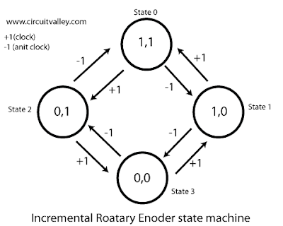
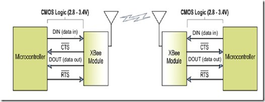
In this tutorial, I will show how to interface an xbee module with PIC microcontroller.Here MikroC Pro for PIC compiler is used to write the code. Xbee modules communicates with host devices using serial communication.Most of the PIC microcontroller have UART module to support serial communication.
First of all we have to understand the two operating mode of xbee.
- Transparent Mode
- API Mode
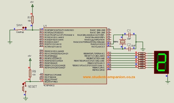
![Interfacing xbee with PIC microcontroller using MikroC]() Interfacing xbee in Transparent Mode
Interfacing xbee in Transparent Mode
In transparent mode two xbee module makes just simple bridge of serial communication.This is like just remove the wire of serial port and place two xbee module.In this mode if you send ‘A’ then another module will receive ‘A’.To send data write this code
void main() {
UART1_Init(9600); // Initialize UART module at 9600 bps
Delay_ms(100); // Wait for UART module to stabilize
UART1_Write(‘A’);
}
To receive this data on the other side write this code
char receive;
void main() {
UART1_Init(9600); // Initialize UART module at 9600 bps
Delay_ms(100); //Wait for UART module to stabilize
// If data is ready, read it:
if (UART1_Data_Ready() == 1)
{receive = UART1_Read();}}
Interfacing xbee in API Mode
API mode is main thing of a xbee module.You can make mesh networking,use of analog to digital pins(IO pins).In this mode all communications take place as structured data frame.Here some examples of data frame are shown:
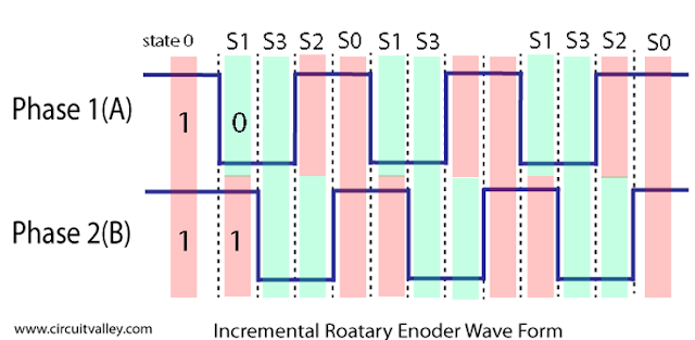
AT Commands
The following image shows the API frame exchange that takes place at the UART when sending an AT command request to read or set a module parameter. The response can be disabled by setting the frame ID to 0 in the request.
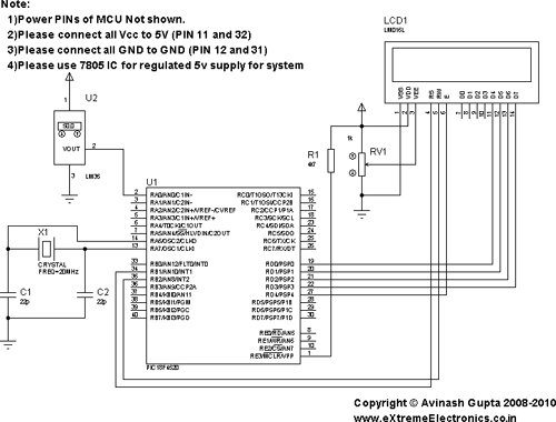
![Interfacing xbee with PIC microcontroller using MikroC schematic]() Transmitting and Receiving RF Data
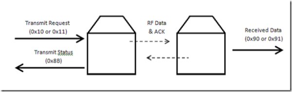
Transmitting and Receiving RF Data
The following image shows the API exchanges that take place at the UART when sending RF data to another device. The transmit status frame is always sent at the end of a data transmission unless the frame ID is set to 0 in the transmit request. If the packet cannot be delivered to the destination, the transmit status frame will indicate the cause of failure. The received data frame (0x90 or 0x91) is set by the AP command.you can get all the frames structures in datasheet.So we don’t proceed to explain each data frame.Our concern is to send these frames or receive these frames using PIC microcontroller.
Sending API Frames
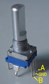
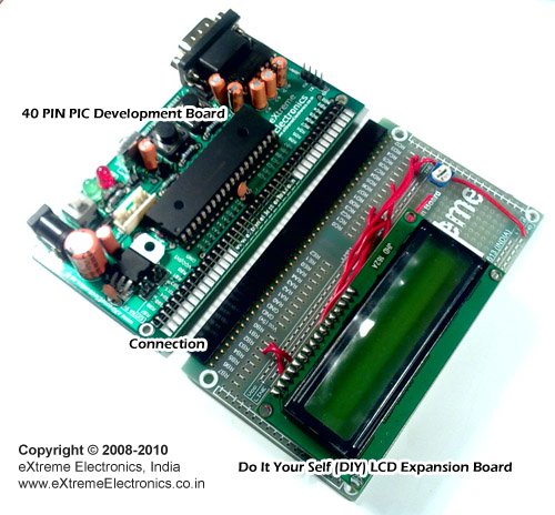
First we will learn how to send data frames from one xbee modules to other.Suppose you have two xbee module.First configure one xbee module as coordinator say it has id 0013 A200 4000 CF30.Another module has id 0013 A200 4000 CF31 is configured as router.Both xbee module is connected with two PIC microcontroller (say two PIC16F73) via uart (Tx and Rx pin).
Now we will send some API frame frame coordinator to router xbee.Before sending API Frame it will be good practice to learn the use of DIGI API Frame Maker.This is an HTML page to build API frames.You can select your desired Frame and it will show you the structure of the frame with its functions.You can also put the desired values in various fields and it will build frame packet that you can use to write code.Another way to make data frame is to read xbee data sheet,each data frame is explained in data sheet.But I highly recommend you to use DIGI API Frame Maker as it is easy to use.
Transmit Request Frame
This frame is used to send any data to remote module.Suppose we want send “txdata” from coordinator to the router.All will be sent as hex.So we have to convert it in hex format.From DIGI API Frame Maker the data frame will be
7E 00 14 10 01 00 13 A2 00 40 00 CF 31 00 00 00 00 74 78 64 61 74 61 73
7E is the delimiter.Every frame contains this hex value first.
00 14 is Number of bytes between length and checksum fields.
Next byte 10 is API id of Transmit Request frame.
00 13 A2 00 40 00 CF 31 is ou router’s id which is destination address where data will be sent.
Next look at the 74 78 64 61 74 61 is desired data to be sent. This is hex format of ”txdata”.
Now we will write code to PIC which is connected with coordinator xbee to send this frame to router module.
void main() {
UART1_Init(9600); // Initialize UART module at 9600 bps
Delay_ms(100); // Wait for UART module to stabilize
UART1_Write(0x7E);
UART1_Write(0x00);
UART1_Write(0x14);
UART1_Write(0x10);
UART1_Write(0x01);
UART1_Write(0x00);
UART1_Write(0x13);
UART1_Write(0xA2);
UART1_Write(0x00);
UART1_Write(0x40);
UART1_Write(0x00);
UART1_Write(0xCF);
UART1_Write(0x31);
UART1_Write(0x00);
UART1_Write(0x00);
UART1_Write(0x00);
UART1_Write(0x00);
UART1_Write(0x74);
UART1_Write(0x78);
UART1_Write(0x64);
UART1_Write(0x61);
UART1_Write(0x74);
UART1_Write(0x61);
UART1_Write(0x73);
}
This code simply sends a data frame with data “txdata” from coordinator to router.Now router module will receive this frame as Receive Packet Frame(frame id 0x90).We will discuss later how to write code to receive this data in the PIC microcontroller connected with the router module.
Remote AT Command
This frame is used to change any setting of an xbee module from a remote xbee module.Suppose you want to change the state of a digital IO pin(from high to low or vice versa) of your router module from your coordinator module.Here a data frame is shown to make the DIO4 pin to high.
7E 00 10 17 01 00 13 A2 00 40 00 CF 31 00 00 00 44 34 05 75
Look at 44 34 05.
44 34 means D4 which is defined AT command DIO4 configuration.
05 stands for output high.If you want to make it output low then it will be 04.
17 is the Remote AT Command Frame ID.
00 13 A2 00 40 00 CF 31 is the ID of our router module.
Now write the following code in PIC which connected to the coordinator module
void main() {
UART1_Init(9600); // Initialize UART module at 9600 bps
Delay_ms(100); // Wait for UART module to stabilize
UART1_Write(0x7E);
UART1_Write(0x00);
UART1_Write(0x10);
UART1_Write(0x17);
UART1_Write(0x01);
UART1_Write(0x00);
UART1_Write(0x13);
UART1_Write(0xA2);
UART1_Write(0x00);
UART1_Write(0x40);
UART1_Write(0x00);
UART1_Write(0xCF);
UART1_Write(0x31);
UART1_Write(0x00);
UART1_Write(0x00);
UART1_Write(0x00);
UART1_Write(0x44);
UART1_Write(0x34);
UART1_Write(0x05);
UART1_Write(0x75);
}
If you place a led in DIO4 pin of router module then it will glow.
Receiving API Frames
Let’s talk about how to this frames we already sent.Recall the data frame Transmit Request.When you send this frame to router from coordinator,after receiving this frame router module send a frame to PIC microcontroller via uart called Receive Packet Frame(ID 0x90).The structure of the received frame will be
7E 00 12 90 00 13 A2 00 40 00 CF 30 00 00 00 74 78 64 61 74 61 F5
Look at the frame.
90 is the frame id.
00 13 A2 00 40 00 CF 30 is sender address(Our Coordinator address)
74 78 64 61 74 61 is desired data which is received(recall “tadata”).
Now we write code to receive our data from the frame.
MikroC gives a built in function called
void UARTx_Read_Text(char *Output, char *Delimiter, char Attempts);
It reads characters received via UART until the delimiter sequence is detected. The read sequence is stored in the parameter output; delimiter sequence is stored in the parameter delimiter.For example:
UART1_Read_Text(output, “OK”, 10); // reads text until OK is found
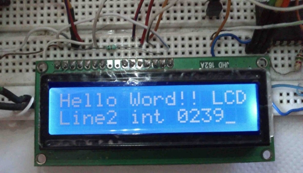
Here our delimeter is ‘~’ sign.So we will write the code
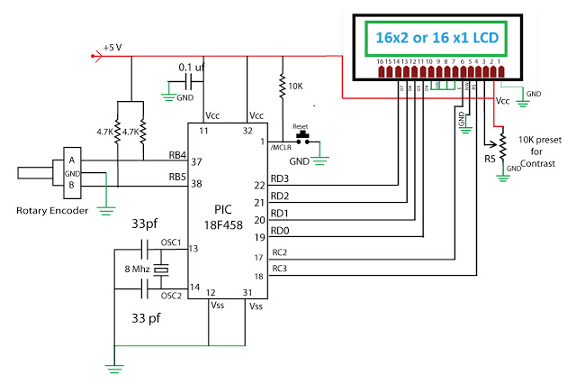
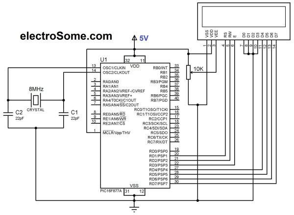
// LCD module connections
sbit LCD_RS at RB4_bit;
sbit LCD_EN at RB5_bit;
sbit LCD_D4 at RB0_bit;
sbit LCD_D5 at RB1_bit;
sbit LCD_D6 at RB2_bit;
sbit LCD_D7 at RB3_bit;
sbit LCD_RS_Direction at TRISB4_bit;
sbit LCD_EN_Direction at TRISB5_bit;
sbit LCD_D4_Direction at TRISB0_bit;
sbit LCD_D5_Direction at TRISB1_bit;
sbit LCD_D6_Direction at TRISB2_bit
sbit LCD_D7_Direction at TRISB3_bit;
// End LCD module connections
char output[30];
void main() {
Lcd_Init(); // Initialize LCD
UART1_Init(9600); // Initialize UART module at 9600 bps
Delay_ms(100); // Wait for UART module to stabilize
while(UART_Data_Ready() == 1)
{
UART1_Read_Text(output, “~”, 35); // reads text until OK is found
Lcd_Chr(1, 1, output[14]);
Lcd_Chr(1, 2, output[15]);
Lcd_Chr(1, 3, output[16]);
Lcd_Chr(1, 4, output[17]);
Lcd_Chr(1, 5, output[18]);
Lcd_Chr(1, 6, output[19]);
}
When the frame is received output[] array will be filled with the frame data.Our frame was
7E 00 12 90 00 13 A2 00 40 00 CF 30 00 00 00 74 78 64 61 74 61 F5
So output[] sequence will be
output[o]=0x00
output[1]=0x12
output[2]=0x90
output[3]=0x00
output[4]=0x13
output[5]=0xA2
output[6]=0x00
output[7]=0x40
output[8]=0x00
output[9]=0xCF
output[10]=0x30
output[11]=0x00
output[12]=0x00
output[13]=0x00
output[14]=0x74
output[15]=0x78
output[16]=0x64
output[17]=0x61
output[18]=0x74
output[19]=0x61
output[20]=0xF5
So we just need
output[14]=0x74
output[15]=0x78
output[16]=0x64
output[17]=0x61
output[18]=0x74
output[19]=0x61
Which is printed in LCD in the above code.
Source : Interfacing xbee with PIC microcontroller using MikroC
The post Interfacing xbee with PIC microcontroller using MikroC appeared first on PIC Microcontroller.
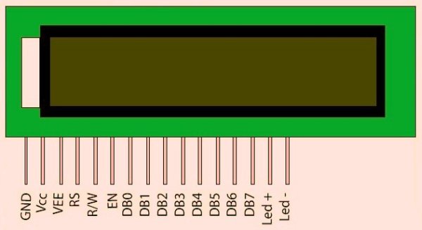
 Pin description
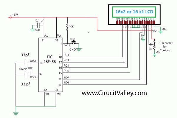 Function Set